A. A smartphone is a device that has become an indispensable communication device for all people. They are used to access the Internet and often for a long time. But smartphones have one drawback - time. battery life. In the best case, the battery will work without recharging for one day, and if you use it actively, then for several hours. This article and accompanying video show you how to make a powerful homemade Powerbank that can even charge your smartphone or tablet or a combination of both simultaneously.
You can buy the baby monitor, which is described at the beginning of the video, and all the components of the power bank in this Chinese store. Information on how to receive cashback (refund) in the amount of 7% of the price of all purchases is on our website. Download the schematic, board and other project files.
In order to improve the performance of mobile phone batteries, portable chargers were ordered, which are popularly called power banks. But in its single form, such a device is not even half capable of charging a phone battery. And even three such devices do not provide a way out of the situation. Buying a powerful power bank is quite expensive. A normal powerbank, say, with a capacity of 10,000 milliamps costs 25-30 dollars. Considering this and the long waiting time for the parcel, it is easier to make your own option.
Description of the power bank circuit
The powerbank circuit consists of three main parts. This is a lithium battery charge controller with an auto-shutoff function when fully charged; battery compartment with parallel-connected 18650 lithium-ion batteries; 5-10 amp power switch from the computer power supply; a boost converter in order to increase the voltage from the battery to the desired values of 5 volts, which are needed to charge a phone or tablet; USB connector to which the device to be charged is connected.
In addition to its simplicity and low cost, the presented circuit has high output current values, which can reach up to 4 amperes and depends on the rating of components such as a field-effect transistor, a Schottky diode at the output and inductance. Chinese analogues are capable of providing an output current of no more than 2.1 amperes. This is enough to charge a couple of smartphones at the same time, and our power bank can handle 4-5 smartphones.
Let's look at the individual components of the structure. The power source is 5 parallel-connected 18650 batteries from a laptop. The capacity of each battery is 2600 milliamps per hour. The housing used is from an adapter or inverter, but another suitable housing can be used. We will use a charging board purchased as a charge controller. The charging current is about 1 ampere. You can also take a ready-made inverter that will increase the voltage from the battery to the required 5 volts. It's very cheap. Maximum output current up to 2 amperes.
Circuit assembly
At the first stage, we fix the batteries and fasten them together using a glue gun. Next, you need to connect the controller to the battery to check how the charging process occurs. You also need to find out the battery charge time and understand whether auto-shutdown works when fully charged. Everything is labeled in detail on the board.
You can charge from any USB port. The indicator should show that charging in progress. After 5 hours, the second indicator lights up, which means the charging process is complete. If a metal case is used, the batteries should be additionally insulated using wide tape.
One of the main components of the circuit is a step-up dc-dc converter, an inverter - voltage converter. It is designed to raise the voltage from the batteries to 5 Volts needed to charge the phone. The voltage of one battery is 3.7 volts. Here they are connected in parallel, so an inverter is needed.
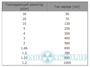
The system is built on a 555 timer - a field-effect transistor and stabilization of the output voltage, which is set using a zener diode vd2. Zener diode may have to be selected. Any low-power zener diode will do. Resistors of 0.25 or even 0.125 watts. Inductor L1 can be removed from the computer power supply. The diameter of the wire is at least 0.8, it is best to make 1 millimeter. The number of turns is 10-15.
The circuit contains a frequency-setting unit that sets the operating frequency of the timer. The latter is connected as a square pulse generator. With this selection of components, the operating frequency of the timer is about 48-50 kHz. Gate limiting resistor R3 for a 4.7 Ohm field effect transistor. Resistance can be from 1 to 10 Ohms. You can replace this resistor with a jumper. Field-effect transistor any medium power with a current of 7 amperes. Field crops from motherboards. Small reverse conduction transistor vt1. A kt315 or other low-power reverse conduction transistor will do. Rectifier diode - it is advisable to use a Schottky diode with a minimum voltage drop across the junction. Two containers serve as a power filter.
This inverter is pulsed, it provides high efficiency, high output voltage stabilization, and does not heat up during operation. Therefore, there is no need to install power components on the heat sink. If there are difficulties with Schottky diodes, then you can use diodes that are in computer units nutrition. Dual to-220 diodes are found in them.
The photo below shows the inverter in assembled condition.

Can be done printed circuit board. There is a link in the description.
Testing a 5 volt inverter
We check the inverter for functionality. The smartphone is charging, as you can see, the charging process is in progress. Output voltage is kept at 5.3 volts, which fully complies with the standards. The inverter does not heat up.
Final assembly into the body
We need to cut out the side walls from a piece of plastic. There are two charges on the controller LED indicator, which show the percentage of charge. They need to be replaced with brighter ones and displayed on the front panel. There are two holes cut out in the side wall for micro USB connectors, which means you can charge two devices at the same time. There are also holes for LEDs. A hole for the controller, that is, for charging the built-in batteries. A small hole will also be made for the power switch.

All connectors, LEDs and switch are fixed with a glue gun. All that remains is to pack everything into the case.

A USB tester is connected to the output of the device. It can be seen that the output voltage remains firmly at 5 volts. Let's connect mobile phones and try to charge them from a homemade Power bank. Two smartphones will be charged at once. The charging current jumps to 1.2 Amperes, the voltage is also normal. The charging process is progressing successfully. The inverter works flawlessly. It turned out compact and, most importantly, stable. The circuit is easy to assemble; familiar components are used.
Sometimes, there are situations when you need to charge your phone or camera, but there is no outlet nearby. In this case, a device called " power bank”.
Such a device usually consists of a pair or three small batteries, a charger for them and a voltage converter for the device being charged, be it a flashlight, a mobile phone or a camera.
I took the batteries from an old laptop battery, size 18650, to charge them I decided to use the Chinese TP4056 microcircuit, specially designed for charging Li-Ion batteries, and bought a boost converter built on the CE8301 microcircuit in the form of a ready-made module. Microcircuits and modules, ordered on eBay.com.
TP4056 has a number of positive features, namely:
1. Protect batteries from overcharging and overheating
2. A small number of external elements
3. Indication of operating modes
4.Adjustable charge current
5. Low cost
6. Etc. and so on.
Connection diagram TP4056

The charge current is adjusted by resistor Rprog. I set it to 2.2 kOhm, charging current 500mA.
CE8301 has a million similar analogues, you shouldn’t get too hung up on it, I’ll just say that it works from 0.9V to 5V, while the output holds 5V 500mA (600mA maximum), which is quite enough to charge most mobile phones and cameras.
CE8301 connection diagram

Photos of converters

I wanted to make the finished device quite functional, so I decided to use 2 converters if I had to charge a couple of devices at once, and for batteries I decided to take as many as 4 TP4056 chips so that I could use batteries with different capacities.
To ensure that the TP4056 microcircuits do not influence each other, the batteries are connected through Schottky diodes, with a drop of 0.2 Volts.
The final diagram looked like this


Made

Checked

And installed all the components


The black droplets with the inscription 103 are 10 kOhm thermistors.
The board turned out to be quite compact, taking into account the fact that only 10 µF capacitors and TP4056 microcircuits were used from SMD components. When soldering, I placed pieces of masking (paper) tape under the housing of the microcircuits so that the heat sink of the microcircuits did not short out the tracks.
The circuit works great, nothing gets hot. During charging, the red LED lights up, when the battery voltage reaches 4.2V, the red LED goes out and the green LED lights up - charging stops. If the thermal protection has tripped, the LEDs do not light up, and if there is no battery connected to the circuit, the green light is on and the red flashes. Charging of cans of the same capacity and with the same residual voltage occurs quite synchronously. In general, I got exactly what I wanted.
Everyone brainiacs, Hello! I suppose you all belong to that part of the world's population that uses smartphones, and I think over the past couple of years you have replaced them several times with more advanced ones. All “outdated” smartphones have lithium-ion batteries, which are not possible to use in new models, and thus you are left with good, but useless batteries... Is this true?


Personally, I have accumulated three phone batteries (and I did not change the phones because the batteries were faulty), they did not heat up or swell, and they can be used to power some gadgets. The capacity of an average battery after 2 years of use is about 80% of the original, this is exactly the period during which I usually purchase a new one brainsmartphone. And if you think about the efforts to obtain raw materials, the production of the batteries themselves and the costs of transportation...
All things considered, it would be a real shame to let them slowly "die" or simply throw them away. In this brain article And video I'll tell you how with your own hands do homemade, which allows you to “give new life” to batteries from old phones, that is, make an external battery for gadgets, also known as POWERBANK.
Step 1: Materials


Well, let's start with what you need to create your own external battery. Materials needed:
- lithium-ion battery,
- charging and protection board for lithium-ion batteries, designed for 5V, maximum input current 1A (the less, the longer the “second life” of the battery will be),
- DC/DC boost converter with output values of 5V and max. 600MA
wires, - several pin connectors,
- stationery clip,
a piece of acrylic, - screws,
- and a switch.
You will also need:
- a pair of pliers,
- stripper,
- soldering iron,
- and a glue gun,
- and also a drill and a drill.
Step 2: How do the boards work?


First, let's take a look at the charging and protection board for lithium-ion batteries. Three of her important functions These are charging, overcurrent protection and too low voltage protection.
Lithium-ion batteries charge according to a specific pattern - when they are almost fully charged, their current consumption decreases. Brain board recognizes this and as soon as the battery voltage reaches 4.2V, it stops charging. At the output of the board there is a protection circuit that prevents overcurrent and excessive undervoltage. Modern telephone batteries already have such protection built in, but in this case homemade This board will allow you to use unprotected batteries that can be found in older laptops. The charging current of the board can be adjusted using a resistor, and it should be within 30-50% of the rated battery capacity.
The DC converter converts the battery's DC voltage into a square wave and passes it through a small coil. Due to induction processes, more high voltage, which is converted back to DC and can be used to power gadgets designed for 5V.
Now, more or less knowing what we are dealing with, we can begin the actual assembly brain games.
Step 3: Design


Before you start creating the housing for homemade products, measure the components and make a drawing. So in my brain structure the battery will be secured using a stationery clip, which is screwed to the case, the boards will be located on top of each other, the input/output contacts will be on top in the upper part of the case, and the contacts going to the batteries will be on the bottom.
Some batteries have a non-standard position of the polarity of the contacts, so this “non-standard” needs to be taken into account in our device, that is, we need to add pin connectors. To do this, take a connector with three pins and tear out the middle one, and bend the pins themselves on one side to make it easier to attach them to the battery contacts. Or take a connector with four pins, connect the outer ones to the positive terminal, and the middle ones to the negative, and thereby change the polarity of the contacts by simply connecting the battery to the left or right pair of pins.
Step 4: Making the Case


Now let's start assembling the body. To do this, take a ruler and use a sharp knife to mark the lines, scratching them about 10 times, so that you don’t have to put a lot of effort on the workpiece and don’t use the ruler anymore. Having scratched the lines to a sufficient depth, we apply pliers to them and bend the workpiece until it breaks along these lines. Having “broken” all the necessary parts in this way braincase, we clean them and adjust them to each other. Then we attach them to a stable surface and, using a drill, make holes and slots for screws, a switch, inputs, outputs and pin connectors.
Step 5: Circuit Assembly

Before you begin assembly brain devices First we assemble the electrical circuit, and focus on the presented diagram. A small switch here serves to turn the converter on/off direct current.
Step 6: Final Assembly


Using a glue gun, we glue the boards to each other, and then to one of the body parts. Next, we glue the entire body and screw a stationery clip to it.
We connect the battery through the pin connector and try homemade In action. If it does not work, then connect the charging cable.
Step 7: Use!


Well, now your old phone batteries are back in business!
The version of the case I proposed is of course not ideal, but it will do for demonstrating the whole concept. I can even bet that you will come up with a much better solution :)
That's all, everyone brain success!
Today, devices such as Power bank (autonomous Charger) have become firmly established in our daily lives. They greatly facilitate the use of all kinds of modern energy-intensive gadgets, such as tablets and smartphones, as they allow you to quickly recharge in almost any conditions when you are away from a power outlet.
The simplest Power banks have only one type of output - USB, which is the most popular. In more advanced chargersdevices you can find outputs with a voltage that has become the standard supply voltage for low-voltage devices - 12V. This is significantexpands the scope of application of such Power banks, since almost any automotive electronics and many others operate from 12Velectrical consumers. And when using an inverter, you can get 220V if desired.
The cornerstone in such Power banks is the issue of capacity. The use of modern high-capacity Li-ion batteries allowscreate in a compact size a power source of sufficient capacity to power any 12 volt device forseveral hours.
Unfortunately, manufacturers often skimp on the quality of built-in lithium batteries to reduce the overall costcharger, which negatively affects the operating time of the Power bank. Therefore, we want to tell you how to make Power yourselfBank using a kit consisting of a multifunctional DC-DC converter, a protection board and housing, and high-quality lithium batteries of a common standard size .
We will need:
Kit for assembling Power Bank model HCX-284 consisting of a multifunctional DC-DC converter and a protection board(PCM) for Li-ion batteries and metal case for 4 Li-Ion 18650 batteries.For lithium cells, we’ll take 4 Panasonic Li-ion batteries model NCR18650B 3.6V with a capacity of 3400mAh
The HCX-284 converter has a stabilized 12V output with a maximum load current of 4A and a 5-volt USB connector with a maximum current of 1A. To charge our Power Bank, you can use any 12V power supply with a 5.5 x 2.5 mm pin connector andmaximum current of at least 1.5A. You can, of course, use less powerful block power supply, but the charging process in this case may takefor quite a long time.
The operating principle of our Power Bank is as follows:
From a battery assembly of 4 series-connected (4S) Li-Ion batteries, we get a nominal voltage of 14.8V. More precisely, thisthe voltage, during operation, will change from 16.8V (fully charged battery) to 12V (fully discharged). Directly toThe batteries are connected to the PCM protection board. It will control these upper and lower voltages, preventing them from going beyondextreme values and protecting lithium cells from overcharging and overdischarging.
From the protection board, the voltage is supplied to the input of the step-down DC-DC converter, which turns our 16.8 - 12V from batteries intostabilized 12V and 5V on the corresponding connectors.
When charging batteries, 12 volts from the “DC In” input of the stabilizer are converted into 16.8 V necessary to charge a 4S Li-Ion battery.The maximum current supplied to the batteries is 1A and does not depend on the power of your power supply. This allows you to useHCX-284 includes lithium batteries with a minimum capacity of about 2000 mAh, the charge current of which should not exceed halfvalues from capacity, i.e. approximately 1A.
Build process:
1. Using hot glue, glue together a battery of four Panasonic Li-Ion batteries model NCR18650B.

Hot melt adhesive is best used withlow melting point to prevent local overheating of batteries. We pay attention to the quality of the adhesive seams - they are notmust protrude beyond the dimensions of the battery, otherwise it simply will not fit into the case.

2. We use special electrical insulators to prevent contact between the nickel welding strip and the battery housing.


3. We weld Li-Ion cells into a 4S battery using 5x0.127mm nickel tape and a resistance welding machine. Solder Li-Ionbatteries are not recommended due to the fact that they are afraid of overheating, which can greatly reduce their service life. Since the currents in our battery will be inwithin 3-4 amperes, this tape thickness will be more than enough.

We immediately form the terminals of all voltages for subsequent solderingwires to the test pins on the PCM board.


4. Install the PCM on the battery. We form power contacts using only tape. It is more reliable and more compact. Test voltagesWe connect to the board with wires of the smallest cross-section. We used MGSHV 0.2mm, but you can use wire and, for example, MGTF0.14mm.


The controller contacts must be connected in sequence from “minimum” to “maximum”, i.e. first “B-”, then +3.7V, 7.4V,11.1V and the last "B+"
5. We make conclusions from the PCM using a 0.5mm PUGV wire. The length of the leads should be no more than 2 cm. Cover the ends of the battery with insulating tape.arton and pack the batteries in thin shrink film.


At this stage, we have a protected battery that can be used without fear of overcharging or overdischarging. But on the way out,for now, we have an unstabilized voltage, which will change during the discharge process from 16.8V to 12V.
6. Connect the battery to the stabilizer board. To do this, connect the black “negative” wire to the “P-” contact, and the red “positive” wire to
contact “P+” In this case, the stabilizer will blink once with all three LEDs.


7. Install the battery with a soldered stabilizer into the case. We start the installation with the battery, then the stabilizer. Stabilizer boardinstalled in special grooves in the housing.


All. Our handmade PowerBank is ready. We check the work by pressing the only button, which, if not connected
connectors, includes a charge level indication, which shows that our batteries are now fully charged.

Let's calculate the total capacity of our Power Bank:
We used 4 Panasonic battery models NCR18650B 3.6V with a capacity of 3400mAh. In total, we get 3.4A/h at a voltage of 14.8V.
But we haveThere are 2 voltages at the output: 5V and 12V. It should also be taken into account that the efficiency of the converter is about 90%.
Accordingly, at 5V the capacity of our
battery will be ((14.8*3.4)*0.9)/5 = 9.05Ah This means that with a five-volt load of 1A current, our Power Bank will work for about 9 hours!At 12V the capacity will be: ((14.8*3.4)*0.9)/12 = 3.77Ah
That's basically the whole process. In terms of time, if you have experience and tools, it takes about 1 hour.
If you are not confident in your abilities, we can Power Bank using any Li-Ion batteries present inour catalogue.
Our store has already assembled, ready-to-use Power Banks based on the H284 kit.
Solar energy is completely free (for now 🙂), widely available and environmentally friendly form of energy. Many people are familiar with the so-called photovoltaic converters, or solar panels. Their cells are made of special semiconductor materials, and when sunlight hits them, it knocks out electrons, causing them to separate from their atoms. When electrons pass through a cell, they generate electricity.
Power Bank - practice
In general with brief theory finished. And now we will make a powerful and high-quality Power Bank, which collects and stores energy using solar panels, as happens in the previous project. The electricity generated from these panels is stored in a Li-Po battery. Then accumulator battery used to generate the required power supply - stabilized 5 V, which is used in USB gadgets, most often smartphones. The power bank can also be charged from an external 5V source from network adapter at 220 V. Outdoors, it charges itself using sunlight - as intended.
Schematic diagram

Save the diagram to enlarge
Printed circuit board in the archive. The solar cell power bank circuit consists of two parts. The first is a charger based on the MCP73831 and the second is a boost converter based on the LT1302-5, which converts the lithium battery voltage to 5 V.

The MCP73831 is a miniature charge controller for lithium-ion or lithium-polymer batteries. Since the input voltage range is 3.7 - 6 V, any value between these values can be used as an input voltage source. An additional 5 V mini USB input is also included in the circuit to charge the Power Bank from a 220 V network via an adapter when sunlight is not enough. The controller will charge the battery up to 4.2 V fully safe mode. The LED on the controller lights up during the entire charging process.

The second stage is a boost converter that converts the 4V battery voltage to 5V. It is based on the LT1302-5 chip - a DC/DC converter with a fixed output voltage of 5V. Input voltage LT1302-5 may be below 2.2V.

The solar panels used in the project are rated at 6V and 150mA, which provides about 1Wh under ideal conditions. And the lithium-polymer battery here costs 3.7 V and 4000 mA, which can provide about 15 Wh. Please note that charging will take much longer than 15 hours as storage and boost conversion efficiency will be less than 100%. But since solar energy is free, there is no rush.