Introduction
The form of the cube, beaten in other fashions, was taken as the basis for the shape of the future case. However, some limitation was introduced, namely the minimum possible dimensions. Given that the maximum (height) side of the motherboard was 32cm, then the internal volume should be 32x32x32cm. The second condition of the mod was the creation of the most simple and affordable material, for the processing of which no high-tech and expensive processes are needed (laser cutting, airbrushing, etc.). At the beginning, I wanted to create a cube from solid natural wood 16-20mm thick, which can be bought in hardware stores, but, however, in the nearest store the price turned out to be quite high - 300-350 rubles per 1 m 2. The choice fell on ... plywood. Yes, ordinary plywood 10 mm thick. According to calculations, a quite affordable sheet of 1500x750 mm came out for about 150 rubles. In order to hide all fastenings, mistakes and alterations from the sides of the mod, it was decided to make decor panels from 5mm plywood on top of the inner case.
In principle, the whole mod process is clear from the photos. But I'll make some clarifications:
Fig.1-3. Round cables from the power supply. I decided not to use standard molexes, but used 4-pin round connectors purchased from Mikronika. The shower hose is attached to the molex with a paper clip, and the connector itself is screwed into the plastic seal of the same shower.
Fig.4. Placement of components in the power supply bay. The power supply is located upside down under the motherboard. The air passing through the power supply is blown into the bottom of the cube by a 120mm fan. A cheap compressor also found its place in the power supply, but I did not decide to experiment with connecting it to the general power supply, but simply pulled its cable out of the case, being able to turn it off if necessary.
Fig.5. One of the IDE power cables has not been disconnected and has been routed to a connector so that it, along with the motherboard power cables, comes out of the power supply. Below them are the device power sockets and a glued water block power connector (+3V removed from SATA).

Fig.6. back wall with sawn holes for motherboard and expansion boards. In the center of the power supply comes a socket for a 220V power cable. Two grilles from old cheap speakers turned into a protective mesh.
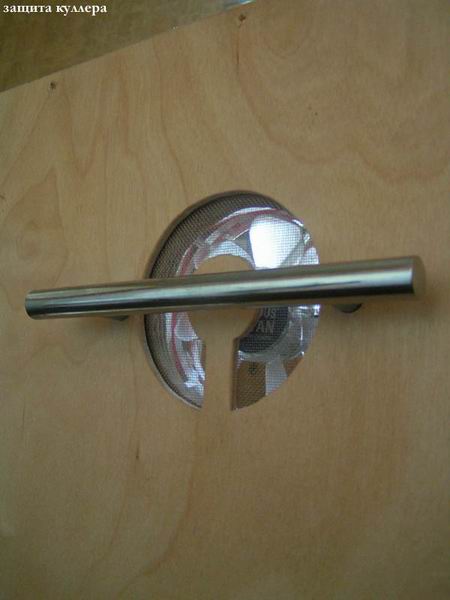
Rice. 7. Illuminated case fans are protected not only by the handle for carrying the cube, but also by a metal mesh (bought from IKEA). The grid is located between the inner case and decor panels.
Rice. 8. The flip-top lid holds a DVD and a CD-RW. The IDE cable went through the bottom wall of this block so that it remains in the case. On the other hand, a molex connector is embedded in the wall, from which power is already being supplied. An LPT connector for an LCD screen is also embedded in the back wall.

Rice. 9. Water block for bubble mod. To fill in water, a neck cut off from a plastic bottle is cut into the upper wall. Since there was a water cooling device in the future, brass tubes were glued into the milled holes in the lower part, on which the shower hose (fitting?) is held. An aquarium atomizer was glued into the back from the bottom - it gives more bubbles than just perforating the tubes. A panel with the necessary buttons and switches will be attached close to the large through hole on the inside. Six UV diodes are responsible for the illumination of the water block.

Rice. 10. Front panel. Rear view :) It has: reset and power buttons, two switches for backlighting the water block, two USB port, 3 variable fan control resistors and 10-LED HDD operation indication. Since the POWER, RESET and HDD LED contacts are already grouped together on the motherboard, using a stranded wire and a USB connector, it was possible to minimize the number of wires.
Fig 11. Actually internal layout. Part of the air blown into the case by the right fan is taken in by the turbine cooler of the processor. Winchester is hidden under the wires on the left wall.
Fig.12. The case in the switched on state without the front decor panel.

Fig.13. The work of bubbles in the water block
Fig.14. Housing without decor panel in night mode.
Fig.15. Front decor panel with holes for DVD-CD-RW and water block. To achieve highlighting of the contour in the lower part, the cut out part is glued with super glue to the metal mesh. I also immediately cut out the stealth panels for DVD and CD-RW.
Final hull photos
Fig.16 - night building
Fig.17 - daytime
Fig.19 - DVD tray with stealth panel attached.
Fig.20 - front panel.
Anton aka \u003d SNAKE \u003d
antogor (a) pochta.ru
25
/10.2005
Good afternoon, Khabrovites. Thank you very much for the invite! And although it’s not a good idea to start by translating other people’s posts, perhaps this homemade project will seem mega-cool to someone else.
This is a translation of a post from the Overclock.net forum. Show4Pro user decided to take out all the insides of his super computer and hang everything on the wall. Great idea beautifully executed. Who cares how it was going and how it works - wellcome under cat.
The last time I upgraded my home machine was 1.5 years ago. Well, I thought to upgrade the car to i7 (before that there was Bloomfield), although in fact, more powerful processor I didn't need. I wanted to buy a new case - Corsair 900D, to change the 8 year old Super Armor. But I wanted something special, unique. In Battlestations on Reddit, I came across a very simple yet elegant solution - a wall mount computer. And that's where the whole project started.
Accessories:
CPU: Intel Core i7 950
Motherboard: Asus Rampage III Extreme
Video cards: 2 x AMD HD7970
RAM: 6 x 2GB Corsair Dominator
SSD drives: 4 x 120GB Corsair Force GT SSD
HDD drives: 2 x 1TB WD Caviar Black
2TB WD Caviar Green
1.5TB WD Caviar Green
Power supply: Corsair AX1200i
Sound: creative sound Blaster Zx
Cooling:
Cooling for CPU:
Water Cooled CPU Heatsink EK Supreme HF Full Copper
Pump Swiftech MCP655 /w Speed Control
Cooler FrozenQ Liquid Fusion V Series 400 ml Reservoir - Blood Red
XSPC RX360 Performance Triple 120mm Radiator
GPU cooling
Heatsink for video card EK FC7970 - Acetal+EN
The pump and cooler are the same as for the processor.
Swiftech MCP655 /w Speed Control
FrozenQ Liquid Fusion V Series 400 ml Reservoir - Blood Red
Watercool MO-RA3 9x120 LT Radiator
Other:
Branch pipes for the cooling system
Koolance QD4 Quick Discounnec No Spill Coupling
Bitspower G1/4 Silver Triple Rotary 90deg Compression Fittings
Monsoon Free Center Compression Fittings
Phobya Angled Clip 90° Tubing Guide
Phobya Terminal Strip Tubing Clip/Holder
Cooling tubes themselves (red) PrimoChill Advanced LRT Tubing Bloodshed Red
Refrigerant phosphorescent, blue EK UV Blue Non-Conductive Fluid
Cables:
Bitfenix Alchemy Premium Sleeved Extensions
Corsair Individually Sleeved Modular Cables
Creation.
First, I took photos of all the components in their real size and put it all together in Photoshop. This way I was able to move them around the work surface and decide what it would look like. Well, this is necessary for wiring the cooling pipes. Here are a couple of layouts:
I refused this, because of the empty space in the lower right corner. And the motherboard turned out to be on the left, although it should be in the very center and draw attention to the entire panel. 
There is also a lot of space on the right, although the power supply and motherboard are already closer to the center. In the final version, the cooling pipes stretch along the entire right edge, plus two thermometers appeared there.

I transfer the motherboard drawing to an acrylic sheet.

Since the video adapters will be far away from the motherboard, I ordered PCIe slot extensions for each of the cards on eBay. This is me testing how they work. True, then I had huge problems with the crossover of cards due to cheap unshielded wires. They were on top of each other and created serious interference. The system hung on loading BIOS. It was possible to launch it with only one card. In the end, I had to fork out for very expensive cables with good protection. But more on that later.

The product has arrived!

Most of the water cooling comes from Performance-PC. They even gave me a T-shirt and two whole mouse pads!

Acrylic substrate for the motherboard.

All acrylic panels are cut at 45° to achieve a glowing edge effect.

The holes are drilled, the fasteners are installed.
TA-dah!!! It turns out that the mother of Rampage III Extreme is eATX format. And this is for the ATX form factor.
I made the correct eATX substrate later.

Time to gut my dusty old hull.


In the old computer, the disks are inserted into Vantec HDCS boxes, which make 3 HDD boxes out of 2 5.25" boxes.


Video cards.
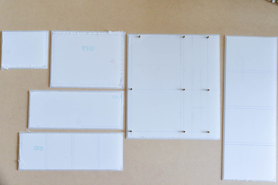
Substrates for all components.

Custom acrylic pump mounts.

Close-up of a rough finish made with a table saw. Later they will need to be sanded.

There is a triangular cut in the center of each plate. It will reflect light that is projected perpendicularly inside the plate at the edges. Without a cut, the edges barely glow.


Test with the light on on the sound panel.

All panels are sanded with 120 grit sandpaper.

Close-up of grinding.
All back panels are pre-drilled.

Under the table - acrylic snow.

Preparing to paint red.
Surprisingly, Corsair did put thermal pads on the petals, even though they don't get hot at all.

Marking all the components on the main board to mark the various slots and holes. Board - 1/4 "48 x 30 fiberboard.

All slots and holes are marked in their places.

I'm getting ready to cut the slots with a jigsaw.


I glue the frame.


I paint the inner edges black - the color of the carbon film.


Soldering LED strips.

Workplace.


LED strips. Temporary fastening.

Gluing a giant vinyl film. This was the most brutal part. I almost got a heart attack. How to stick a film on a phone screen, only x1000 more.

No bubbles!


I use aluminum tape to hide the LED on the front side of the hard drive panel, between them.

My assistant is Tommy.

All substrates are installed in their places on the common board with screws No. 10. They were screwed into pre-prepared holes.


Light check.

The coolant and cables have arrived. I used Bitfenix for the components and Corsair for the power supply.


On the left is Bitfenix, on the right is Сorsair. Bitfenix doesn't have black heat shrink on the ends, so the Corsair looks cooler.

Red ties to tighten hanging wires.

Backside. All cables are connected.

We test for leaks while the entire system is on the floor - it's easier to fix problems.
First start.
Not loaded. I connected via iROG USB to my laptop to see the download log. It turned out that the system was stuck on the VGA BIOS. Disconnected one of the video cards - everything worked. Tried to connect another - also works. Both cards are not. Did a little research and found that unshielded PCIe extenders with ribbon cables are very susceptible to EMI. I tried to shield them by wrapping them in several layers of aluminum foil. 

After 4 layers of foil, I was able to run both cards. But the car immediately hung as soon as it launched any game or some 3D editor. Not only that, my Soundblaster is also cascaded to a 3 x1 PCIe slot, and this also greatly interfered with the operation of the video cards and hung up the system.
As a result, with pain in my heart, I had to order expensive protected extenders for PCIe slots from 3M (about $100 each)

Shielded 3M extensions in place. They turned out to be longer than the previous ones and now both video cards have reached PCIe x16.


Changed the previous sound to SoundBlaster Zx. This one looks amazing!

And finally
On this moment everything works smoothly. The unit has only 2 fans. On the PSU, it barely moves, and I put another one on the chipset - very quiet. The pump runs at the lowest power, so the computer came out pretty quiet. The only thing that irritates is that it turned out that the work of some components is heard outside the case. In my case, this is the buzzing of the video and 1TV hard drive.EK UV refrigerant is very sensitive to ultraviolet light. I know you shouldn't mix coolants to preserve their properties, but gosh, if I used it undiluted, I wouldn't be able to see the coils in the tank. For both circuits, I took about 1/8 of the can, the rest is distilled water.
From the translator
I do not pretend to at least some authorship of this incredible project. It's just that I'm a journalist, with an education in electronics, and doing such things is my dream. And to be honest, I would make a table, not a wall. So I decided, all of a sudden, not all Khabrovites are sitting on
In the age of computer technology, it is impossible to imagine life without a computer or any other multimedia gadget. Those who understand computer "hardware" assemble their own computers, giving them certain characteristics that they need to perform their tasks. Some modify their computers, so to speak, in their own shirt, and some go further and make system units in various variations. So the author decided to independently upgrade his system unit, giving it an exclusive, attractive and creative look.
For the basis of the system unit, the author used a wooden rounded square. This can be found in subwoofers. They are, of course, longer, but if you have a hacksaw for wood or a grinder attachment, it will not be difficult to reduce its size to the one you need.
the next step is to make a groove around the entire perimeter of the workpiece into which the wall will lie system block. To do this, you will need a chisel and a hammer. If the farm has a cutter, then things will go even faster, and the result will be much better.


Next, in the upper part of the workpiece, we begin to cut an opening for two fans using an electric jigsaw. If you have more and space, you can install more. Won't hurt. The place of the future drank is marked and either electrical tape or masking tape is glued along the border of the saw cut. This is to ensure that there are no chips and burrs on the surface. A hole is drilled for the jigsaw blade and sawed out. We insert the fans and see how they are located. If everything suits you, then good. If not, we bring to mind - we grind and so on. For further work it is necessary to remove them and put them aside for a while, because. when carrying out other work, they will interfere with you.

Next, we determine where and in what order you will have the rest of the connectors - USB, a place for hard drive and so on. Everything is cut in the same way as described above.

One of the walls of the system unit is installed.

Next, install all the components. Fasten everything to small wood screws.

The metal wall is attached to the base and fixed. From the inside, they are also attached to the corners.


Now a hole is drilled in the wall for the power button.

We assemble and fasten the strips on which all the connectors are located.

Next, we make the legs. They are cut from the same material that you use to build the hull. We glue them to the bottom and wait for drying. For a stronger connection, you can drill through holes in the legs and non-through holes in the body. And put it all on self-tapping screws.

connect the power button and install the wall in place.

The author made the second wall from dark transparent plastic. Placed around the perimeter led strip. When you turn on the computer, it lights up and all the insides are visible. Quite beautiful and unusual. When turned off, the system unit has a strict appearance.
... in fact, it all started many years ago, about 78 years old, when I was four years old ... Coming to visit relatives, I got a large iron box with tools, light bulbs, switches and this kind of "junk", after which I throughout the “visiting trip” I was not seen or heard. By the way, the owner of that box, my uncle, is very straight arms...
Currently I work as a foreman in a carpentry section, the craving for everything that contains microcircuits has been pursuing for a long period of time, but from the moment I purchased the first computer, thoughts “to do something with it” systematically appeared in my head. Then I found out what modding… And from that moment there is not a day that would not think about it ... By the way, this is my first job ...
Enough introductions, let's get straight to the point. Every mod starts with a lot of thinking about what I want to do. As a rule, I don’t make drawings (but in vain :)), many thoughts come during the work. Unfortunately, at the time of the start of the mod, I did not think that I would show my work somewhere (on the Internet), so there are not very many photos ... Well, let's start ...
Of course, it all started with the search for the case of the system unit, a damaged case of unknown origin was bought, which served as the basis for the system unit. In my thoughts it was to make a wooden case and, moreover, not to be ashamed to show it to my friends, but since this is my first work, I decided to stick with the classic layout. Iron was bought all new, here is a list of what was used
CPU Core 2 Duo E8400, 3000 MHz (9 x 333)
Motherboard Asus Maximus Formula
Memory OCZ XTC SLI OCZ2N800SR2G * 2 pcs
Video ATI Radeon HD 3870 (RV670)
Sound adapter Analog Devices AD1988B @ Intel 82801IB ICH9
Sound adapter C-Media CMI8738/C3DX Audio Device
Disk Drive ST3500320AS ATA Device (500GB, 7200RPM, SATA-II) * 2 pcs
TSSTcorp CDDVDW SH-S202H ATA Device Optical Drive
power unit CHIEFTEC CFT-500-A12S
CPU cooler Noctua NH1-U12P
Fans thermal take Cyclo Blue Pattern A2450*2pcs
I do not count the numerous LEDs, neon lights, wires, etc. Of the tools, those that are in any carpentry workshop were used ... Unfortunately, I don’t have a dremel ... For now ...
Actually, I started with re-gluing the front panel, base and cover of the system unit. In carpentry, the most important thing is not to forget the golden rule measure seven times, then measure again and only then cut off, Therefore, we will cut off everything superfluous later.
Here is a photo of the future front panel:

I'll make a few clarifications. For the top cover and front panel, I re-glued oak shields and drove them to a thickness of about 17-22 mm, then glued the laths along the edges. I made markings on the front panel by attaching it to the iron frame of the system unit, after which a hole was made for the 120th fan with a ballerina and a manual jigsaw. Next, we make side walls from plywood


On following photos you can see how the side wall will open. Plus - when the wall is removed, it opens good access to all internal components system unit, minus - In order to open it completely, you need to move the case away from the wall ... Fortunately, you don’t have to open it often ...


When the blanks are ready, the fitting of all the details of the future body to each other begins. As well as finishing all sorts of little things ...

Subsequently, they should receive a practically assembled body, ready for further processing (grinding, painting)


After some time (it was a lot of work) I start fitting the frame of the case. The fact is that the fans did not climb, I had to cut it a little. Well, since I don’t have a dremel, we use a grinder (do not forget about safety precautions)

And cutting off everything that bothered us

Let's start preparing the frame for painting. Due to limited funds, it was decided to confine ourselves to sanding and the actual painting itself ...

While the first layer of paint dries on the side wall, cut out the window (jigsaw, hands) and put the pre-cut glass on gluing

Of course, the painting process takes a lot of time, the intermediate layers need to be sanded (sandpaper 500-600), painted again, etc. and so on. As a result, we get a frame ready for assembly

But not all body parts are ready for assembly, so we are painting the “wooden component”


For some unknown reason, the painting process itself was not photographed, but I can say that everything was painted with DUFA paint. It was opened 4 times with grinding between layers (grain sandpaper 600-800), then it was opened with varnish 2 times ... proceed to assembly ... Photo for some reason, they were also not done, I can only notice that the assembly took place over 2 months (the motherboard was missing, I was waiting for it to be brought) While I was in “standby mode”, I took up the power supply.
I inserted blue LEDs, cut out a side window, connected a 7 volt fan ... In general, standard procedures aimed at “improving the appearance and performance properties” of this device. The fans in the case are also connected to 7 volts (front) and 5 volts (rear). The cover of the USB compartment is illuminated, the computer power button is also displayed here

That allowed not to put the power button directly on the front panel. The DVD-ROM tray is also highlighted and a reed switch is installed instead of the opening button (located right behind the stickers that were later removed :))

And finally, the final photos


At present, I am hatching plans in my head to build a case based on the Core i7. Well, of course, I hope this is not my last article, I have also made a test PSU, a mouse (rather, working out the veneering technology).
Did: Mikhail Kopylov
After acquiring a new computer or upgrading an old one, a situation often arises that the computer case itself no longer meets certain requirements. This includes the noise level, the installation of new parts or an additional power supply, cooling. And your old case does not fit all these innovations, or the temperature level rises simply to prohibitive limits. And you start looking for the most affordable solution to the problem: buying a new case or making it yourself, on your own. This article will consider an example of how to make a computer case with your own hands or improve it. If necessary, you can watch the video instructions for making the case, for example:
As you know, when choosing a computer case, you need to think not only about appearance, although the original approach and custom solution are also important. First of all, you need to clearly understand that the case is an integral part of your PC, and not just a beautiful box on the table or under the table. The design of the hull must be approached with knowledge of the matter. First you need to find out what types and types of cases are, their differences and functionality.
To date, only four main types of PC cases are known. There are, of course, many extraordinary solutions, but more on that later. Each of these types has its good and not so good sides, so it is impossible to say unequivocally which one is the best. Just read their advantages and disadvantages so that you have something to rely on in your design. Or, if you decide that you can’t do it yourself, then the criteria will be clear to you by which you can buy a suitable high-quality case from the manufacturer.
There are vertical (tower) and horizontal (desktop) versions of cases. Vertical cases usually allow you to put more drives and all sorts of other devices, while horizontal cases are more compact.

The first case type we will look at is called the Small Form Factor.
This type of housing is distinguished by compact dimensions. It is especially suitable for office computers, or for a home PC if you do not need a particularly powerful system. The dimensions of such a case are very small (about 25x25 cm), which allows it to easily fit into any interior and take up a minimum of space. Such cases have a big minus, such miniaturization requires a suitable "stuffing", small sizes of parts. In such a case, it is no longer possible, for example, to insert a modern powerful video card or processor. In addition, small dimensions can cause cooling problems, components can overheat, causing system failures and breakdowns.

The second type of cases is called Mini-Tower Form
Such a case can already be used for a fairly powerful office PC, or for a home media center. Such cases, as a rule, are initially equipped with power supplies with a power of 400W or more. In such a case it is possible to assemble good system with a dual-core processor, put a powerful video card, but many modern components for this option will have to be chosen on the basis of "mini". Another inconvenience is the need for monthly dusting.
The third type of cases is called Moddle-Tower Form
This case type is the most popular and widespread. In such a case, you can easily place a good ventilation system, several powerful video cards, and put additional hard drives. This case is well suited for those who are not limited by the size of the system unit. This type of case is difficult to fit into the interior, but it provides good system performance and will satisfy the requirements of even avid gamers.

The fourth type of cases is called Big-Tower
This case is very rare to find as a home PC. It is noticeably larger than all the others, and its height reaches at least half a meter. This case can accommodate not only about five good video cards or hard drives, it is suitable for creating servers or a computer that controls other computers in the office. Such a case allows you to place good ventilation in it, which will save the computer from the possibility of overheating. Thus, Big-Tower is ideal for the most advanced users who are engaged in the field of IT technologies and especially demanding gamers.
The first point to consider when selecting or designing a case is whether there is sufficient internal space. It is necessary to determine whether you can place devices there for the necessary cooling of the system unit, installation of fans. It is necessary that air circulate freely inside the case, thereby ensuring the cooling of all parts. Pay attention to the power of the power supply unit (PSU) located in the case or purchased separately. It should be sufficient for the planned PC system. You should also pay attention to the location of the power supply in the case. With high power PSUs, you need to think about its cooling. The PSU only needs to cool itself.
For optimal cooling and low noise, the PSU can be placed according to such schemes.


In the scheme, with the top location of the PSU, we get the following advantages:
- Sufficiently low noise level (19db) when installing a 430W PSU, ARX FD1212-S2142E 12V 0.36A 2400 rpm fan;
- The temperature of the elements rises slightly (+3 degrees in the PSU and +1 degree in the case);
- Standard location;
- Free air outlet.
Such a design can be assembled approximately as in the photo below.

SilverStonetek has launched the production of cases with a lower PSU location.
The advantages of this design are:
- The power supply only serves to cool itself;
- There is no need to redo the PSU;
- Low center of gravity for PC case.

Among the shortcomings, it can be noted: excessive fan noise and difficult air access to the PSU fan.
The body material is mostly aluminum or steel, although many homemade cases are made from wood or Plexiglas. The advantages of the aluminum case include light weight and good heat dissipation. But such a body bends easily and scratches are not uncommon. The cost of aluminum cases is higher than steel ones. The steel case has greater reliability and durability. All parts in such a case will be reliably protected. In addition, steel dampens vibrations better, which reduces the noise of the computer.
When considering different case designs, it is important to first determine which connectors and interfaces you will need now and in the future. Many of the options, such as a thermometer built into the speakers, you do not need, but others simply need it. Here you need to decide for yourself which design and construction to choose, based on the above. And don't forget originality...

Do-it-yourself computer case
So you've decided to make a homemade computer case. This case should allow you to install any possible components in it, give them fast access and provide good cooling. Case options are already possible that provide: almost complete noiselessness, high performance, the possibility of increasing the computing potential, and ease of maintenance. True, such a case cannot be made compact.
The computer case can be made of wood using the technology below.

The diagram shows the location of the main components and the circulation of air flows.
Working drawings of such a building can be downloaded. http://www.easycom.com.ua/downloads/skvorechnik_001.zip
Or look at the picture below.

The computer case is assembled from six walls and one transverse shelf in the middle. The top of the case will house the motherboard, CPU fan, video adapters, and the bottom will house all drives, a floppy drive, a card reader, hard drives, and a power supply. It was decided to equip the lower part with only one 120x120x25 mm fan, since there will be only one element that needs forced ventilation - this is the power supply. In the upper part for normal cooling of video cards and a processor, at least three fans must be installed, with a size of 120x120x25 mm. They are ideally located on the front wall of the future case.
The choice of case material is determined by your capabilities. Plexiglas or acrylic at a cost is quite expensive. Iron sheets, from which it is theoretically possible to make the same hull, are unacceptable, as they will greatly increase the weight of the hull. Already with a sheet thickness of only 2 mm. The manufactured body is likely to exceed 40 kg. And besides, the metal is difficult to process and its cost is also not small.
In our version, chipboard will be used to make the case. These are sawdust pressed into sheets with dimensions of 2660x1660x16 mm (W.L.D.) and impregnated with special glue.
The body parts are marked according to the given drawings and cut out. There is nothing complicated in this, but you can order from those who are engaged in the manufacture of furniture. If you decide to cut the blanks yourself, then you will need essential tool: electric jigsaw and wood saws.

You should get such blanks. Finish the edges well with sandpaper.

When all the blanks are made, you can begin to assemble the case itself. It is necessary to connect and fix the parts according to the drawings. A homemade computer case in a partially assembled case will look something like this.

For the reason that the front panel will be used not only as an “air intake”, but on it there will be buttons for turning on, restarting the computer and all the main indicators ( hard drives and the entire system), they must be embedded in a wooden panel. It is necessary to make holes for all ports, power and reset buttons, indication LEDs. Everything must be done carefully and strictly in size.

LEDs cannot work directly from the motherboard block, they must be connected to it in series with a resistance of 480-500 ohms and a dissipated power of 0.25 watts. All these parts can be bought at any radio store. Wires for connecting buttons and LEDs to the motherboard are soldered into the Q-Connector that comes with ASUS boards. Heat shrink is used as an insulating material. This is a tube made of a special material (polyvinyl chloride), which can change its geometric shape (diameter) when heated. In practice, a piece of such a tube is put on a wire, soldered to another, and the piece of tube is shifted to the place of soldering. After that, it is heated up a little with a lighter. After that, the tube narrows around the soldering point and forms a good insulation. Shrinkage ratio reaches up to 30%.
This means that if the diameter of the tube is 6 mm, then when heated, it will change its value to almost 4 mm. Such a tube can also be bought in any radio engineering stores, and the price is only 2-4 UAH per meter. With such an insulating material, it is desirable to carry out all work related to the installation of wires for the manufacture of this case.

Connectors for power input and output from the ~220 V mains and a backlit power switch are installed on the rear wall of the case.
Should be paid Special attention choice of case fans. They must meet aesthetic requirements, as they will always be in sight. After all, the front panel pays the most attention. It is necessary to select the most quiet fans appropriate for your performance. Therefore, options for the type of gratings "grill" immediately departed.

A Thermaltake Cyclo 12cm Red Pattern or similar fan is well suited for this solution. His choice was determined not only technical specifications, which many fans can envy. This fan operates at a speed of 1500 rpm and at the same time the noise level is not higher than 17 dB, which is characterized as extremely quiet. Another advantage is a kind of animated backlight.

However, you can choose a more "advanced" model from this series of fans, Thermaltake Cyclo 12cm Logo Fan. In this model, as in the Thermaltake Cyclo 12cm Red Pattern, there are no various animated emblems, but the Thermaltake logo is “written”, the approximate temperature of the passing air is shown (built-in thermal sensor), and the relative noise level that the fan creates is also displayed.
All these fans are mounted on the front panel using wood screws in the following way:

To avoid the problem of bending the motherboard textolite, which occurs due to the rigid fastening of the cooler without a special pressure plate, you need to replace this pressure plate with something. You can choose a felt of the required thickness (about 7-8 mm) and cut out a square with dimensions slightly larger than the holes for mounting the cooler of the Socket LGA 775 processor socket. If you look at the height of the stand for mounting the motherboard, then the felt is 1-2 mm higher than it, which gives the necessary rigidity when bending the textolite of the parent stalemate. Felt can be bought at many hardware stores or "from hand" in the markets. The cost of such a piece will be approximately 5 to 20 UAH.

At the very end of the entire roughing of the case, it is necessary to make all the necessary holes in the motherboard shelf through which the power wires, cables of hard drives, disk drives, etc. will pass. First, you need to temporarily screw the motherboard into place and mark and sign all locations with a marker connectors. After that, with the help of an electric drill and a file, all these holes are made.
A self-made case for a computer on the outside of the case is easiest to paste over with self-adhesive. Such material is made of thick paper or a special rubberized oilcloth. The color scheme is limited only by your imagination or the assortment of the store (from pure white color to various wallpapers). This self-adhesive is sold in rolls per linear meter. There are two types of roll width: 450 mm and 550 mm. The cost depends on the complexity of the pattern and width, and usually within 11 - 22 UAH per linear meter. For the manufacture of this case, a shiny black “self-adhesive” was chosen. After calculating according to the drawings, it was determined that five meters of “self-adhesive” would be needed to glue the entire body.
For processing cutouts, another material will be used, double-sided tape with a foam base.

It is necessary as a sealant in places where vibrating components (hard drives, drives) come into contact with the case walls. Foam rubber, from which strips 14-18 mm wide and 2 mm thick are made, is very soft in consistency and shrinks to 0.5 mm, having the ability to also spring. All this is very good for a compactor. The presence of an adhesive substance on both sides allows this seal to be firmly fixed, and individual components to be fixed with it.
It remains to make a "basket" for attaching all drives, hard drives, a floppy drive and a card reader. It is difficult and inconvenient to use a standard "basket", which is installed in serial cases, due to the non-standard location installed devices. You can use a piece of plexiglass 4 mm thick for these purposes. It will not need so much, somewhere a meter by a meter. The cutting of such material is carried out with a manual grinder or grinder. It is not difficult to make all these works. After that, it is necessary to drill the necessary holes in the blanks. Plexiglas is a rather fragile material, and sometimes crumbles if handled carelessly. To drill a hole with a diameter of 3.5 mm in it, you need to perform this operation in three or four passes, starting with a drill with a diameter of 1 mm, and finishing with 3.6 mm. You need to remember to drill out the "nest" for the bolt head to hide it. To do this, you need a drill of such a diameter as a hat. All drives, disk drives and a card reader are attached using the same double-sided tape seal.


To prevent hard drives from transmitting their vibration to the basket, thereby increasing the noise level, you can fix them with four erasers.

When all these operations are done, you can assemble the case. The assembled lower part of the case, with a “basket”, hard drives, drives, a card reader, a floppy drive and an installed power supply, looks something like this:

In a fully assembled form, this case will look like this:

Homemade computer case after testing the computer showed good performance temperature regime. The cost of a homemade case turned out to be much lower than specialized Middle Tower or Full Tower cases. In order to make a computer case with your own hands, you only need certain skills in working with a soldering iron and a special tool.