A two doorbell with indication is well suited for use in a home where there are two gates or doors that are far apart. He helps the person inside the house by different sounds and indication of the number, determining which doors the visitor is standing near. This saves time and effort as there is no need to check both doors. On the site electroschematics.com, this very interesting diagram of a homemade bell for a door was found that functions in such a way that different sounds are played. sound signal, depending on which button SW1 or SW2 is pressed. This is necessary for those who have 2 doors that they can call. With such a call, it is immediately clear which one they are calling.

The alarm will only activate for 1 second, and the display will turn on for 1 minute and then turn off automatically to save power. When powered by 220 V, this is not critical, but it is very useful for a battery bell. The diagram does not show backup power - you can adapt it yourself. Simply remove the transformer along with the diodes and filter capacitors and replace it with a 9 volt battery.
Diagram of an electronic doorbell

Schematic parts list
- Battery or 220V/6V transformer
- D1, D2, D3, D4 - 1N4001
- C1 - 4700 microfarads
- C2 - 470 microfarads
- LM7805
- IC1, IC2, IC3 - LM555 or NE555N
- IC4-74LS02
- IC5-74LS47
- T1, T2, T3 - 2N3904
- R1, R3, R5, R7, R8, R10 - 1K
- R2, R4 - 10K
- R6 - 100k
- R9 - 600K
- 11 to R17 - 330 ohm
- R18 - 100k
- R19 - 5k
- C3 - 100 microfarads
- C4, C6, C8 - 0.01uF
- C5, C7 - 10 microfarads
- C9 - 100 microfarads
- 7-segment common anode display
- Piezo buzzer
The circuit consists of mono- and unstable multivibrators. You can change the frequency of the signal reproduced by the self-oscillating multivibrator by turning the potentiometer R18. The volume of the call is affected by the resistance of the resistor R19. The power consumption of the circuit is 0.2 watts. The current consumption during a call is 50 mA. Printed circuit board not developed - everything is assembled on a breadboard.
In order to equip convenient access to the apartment, you need to understand the scheme doorbell. Today, there are many models of such devices, but at the same time general principle their work remains virtually the same. Consider how to properly install and repair the bell if necessary.
Depending on the type of doorbell, the connection method may vary significantly
Device Features
In each house, to create comfortable conditions at the entrance, a whole list of additional devices is installed. One of them is the doorbell. Its direct purpose is to notify people in the apartment that guests have come to them.
Every person is superficially familiar with the bell device. A call button is attached to the outside of the dwelling, a speaker is installed inside the apartment, which picks up the signal from the button and transmits it in the form of an audible alert. This is how simple models work. IN modern devices functions are significantly expanded up to the transfer of a video image online to Cell phones. Depending on personal preferences, the available budget and the requirements of the owners, it is chosen how to make a doorbell: in the form of a simple add-on or with all available auxiliary features.
Very often, home owners plan to install a bell for a door with their own hands, so it is important to understand what is the scheme of its device and the connection method. To do this, first of all, you should consider the main models that exist on the modern market.

A modern doorbell with a video peephole will ensure home security
Types of calls
Today, the range of products in this group is huge and does not stop expanding. As technology advances, not only external characteristics calls, but also their functionality.
Installing a doorbell is now done in a matter of minutes, as manufacturers have foreseen the device's lightness and ease of use in advance.
There are the following types of doorbells:
- Wired. This scheme is already becoming obsolete. All elements are interconnected by a cable, which somewhat complicates the connection process. The instructions should include a diagram to assist with installation.
- Wireless. Instead of a cord, a radio signal transmission scheme is used and its reception through an antenna. The only wire may be the power supply cable.
- Sound. The signal is sound alert: call, melody, musical composition, voice recording.
- video calls. Connecting a doorbell with a video camera allows you to see what is happening behind the door. Some models are activated only when a button is pressed, while others can turn on, focusing on a motion sensor or broadcast a picture continuously.
- Intercoms. Allow to transfer voice messages both inside the house and outside. Can be combined with a video system.

Types of doorbells depending on the principle of operation
Connection rules
The device is connected in several stages, but before you install the doorbell, you need to carefully consider its location. Please note that the sound of the signal should be heard well in all rooms, this is especially true for private houses. Some models can be supplemented with several speakers that can be placed in different parts of the house. And if there are several inputs, you can purchase an additional call button.
So, how to connect a doorbell:
- Wireless. The wiring diagram for such a do-it-yourself doorbell is the simplest. To get started, install the call button in a convenient location. Then decide where to hang the speaker, taking into account the range of the device, taking into account possible signal obstructions. Elements are fastened with bolts or adhesive tape.
- Wired. Here you need to figure out in advance how to connect the doorbell. Keep in mind that you will have to run a wire connecting both devices, so think over the best path in advance. It is advisable to disguise it in a wall, under a false ceiling or a plinth. From the button there is a wire to the speaker, and from there to the outlet or directly to the mains. For the safety of work, first turn off the voltage in the switchboard. The very principle of connection is as follows: first, the wires for connecting the device (phase and zero) are removed, the power wire is inserted into the housing of the bell speaker and attached to the terminals. The second part is output to the call button, power is supplied to the call and its operation is checked.
- video calls. The main difference is the additional placement of the camera above the door and the screen for receiving pictures.

Wiring diagrams various types doorbells
Repair
If certain problems arose after installation or during operation, you need to know how to fix the doorbell yourself. The most common cause of failures is the departure of contacts. To fix the problem, you need to look at the places of key connections. It can be a button or a speaker inside the house. Sometimes it is enough to pull the wires and the bell works normally again. Much worse if the lead cable is broken. Then it needs to be replaced or soldered.

If the doorbell is used for a long time, contact problems may occur.
There may also be nutritional problems. Then you need to check and repair the power supply and input plugs with your own hands. IN wireless models do not forget to change the batteries in time and monitor the condition of the battery.
This issue is especially relevant for outdoor appliances in a zone with a cold climate and sharp temperature changes.
If you understand the device of the call, there will be no problems with installing it yourself. In addition, if a problem occurs, you can easily fix it without the involvement of outside help.
Making a wireless doorbell with your own hands
The author of the solution shares his experience in making a do-it-yourself wireless doorbell activation system using Master Kit modules. After moving to a new apartment, the first thing I decided to do was set up a bell. But this task proved difficult. The fact is that the developer installed a bell button only at the front door, and there was no button at the front door of the vestibule. Since the old bell was electromechanical and turned on according to the scheme through a button, it required the laying of an additional wire. But an attempt to lay a wire in the vestibule was unsuccessful. The walls of the vestibule were made of durable concrete, and an ordinary drill with a hammer function simply bounced off the wall. In order not to spend money on acquiring an expensive professional tool, it was decided to buy a simple Chinese wireless call. Plus, no extra wires in sight. But it also proved to be difficult. Inexpensive calls had poor sound quality and a banal set of melodies that would get boring after the first month of operation. As a result, we decided to temporarily leave our good old electromechanical bell. That would be the end of everything, but the lack external button at the door of the vestibule periodically made itself felt. It was decided to make a wireless call.
https://site/blog/articles/staryj-drug-luchshe-novykh-dvukh
Articles
Making a wireless doorbell with your own hands
After moving to a new apartment, the first thing I decided to do was set up a bell. But this task proved difficult. The fact is that the developer installed a bell button only at the front door, and there was no button at the front door of the vestibule. Since the old bell was electromechanical and turned on according to the scheme through a button, it required the laying of an additional wire. But an attempt to lay a wire in the vestibule was unsuccessful. The walls of the vestibule were made of durable concrete, and an ordinary drill with a hammer function simply bounced off the wall. In order not to spend money on acquiring an expensive professional tool, it was decided to buy a simple Chinese wireless call. Plus, no extra wires in sight. But it also proved to be difficult. Inexpensive calls had poor sound quality and a banal set of melodies that would get boring after the first month of operation. In the end, we managed to find a suitable call with a more or less pleasant sound. Oddly enough, it was electromechanical, only with a built-in wireless module. Everything is great, but the price of this call was disappointing, it cost 9,000 rubles.
As a result, we decided to temporarily leave our good old electromechanical bell. That would have been the end of it, but the lack of an external button at the vestibule door periodically made itself felt. It was decided to make a wireless call.
To implement the project, several devices operating in the 433 MHz band were selected from the range of Master Kit wireless modules: , and .

I think the question immediately arises, what is the MP220V sensor for. Actually, everything is simple, the developer of this sensor, laid in it additional opportunity, namely: with the help of a simple soldering iron manipulation, the sensor turns into a compact built-in power supply with a current of up to 80 mA and a voltage of 5V or 12V to choose from. By default, the module is set to 5V. Since there is not much space in the bell case, it was chosen to power the MP324M receiver.
But every good thing has its drawback, in this case it is the lack of galvanic isolation from the network. Therefore, when setting up, you must follow the rules of electrical safety. And the installation of the circuit should be carried out only in a de-energized state. To transfer this module to the power supply mode, use a soldering iron to transfer jumpers -V, RL and +V, RL to position 1-2. In principle, nothing prevents you from using a board from a 5V adapter cell phone if space permits.
For compactness, the variable resistor of the MP246 Power Module can be removed. By installing a jumper instead of it from a conventional mounting wire or from the output of a DIP resistor, which was actually done.
To assemble the circuit, you will need one DIP resistor with a nominal value of 10-15 kOhm and an electrolytic capacitor with a nominal value of 47 microfarads with a voltage of at least 6V. In principle, the capacitor can be excluded from the circuit. But the duration of the pulse, at the output of the MP324M receiver, seemed to me large, so this chain was installed. By decreasing and increasing the capacitance of the capacitor, you can adjust the pulse duration. Since different bells have a different structure, this may be necessary when adjusting the sound. A resistor installed in parallel with the circuit discharges an electrolytic capacitor, so that the bell can be re-triggered.
Wiring diagram:

After assembling the call control circuit, connect the structure to the network and register the receiver. To register, briefly press the button on the receiver, then press the buttons on the transmitter, pairing will occur after a few seconds. Now when you press the first button on the transmitter, the bell should work. Thus, we add and check the second remote control.
Photo of the layout of the modules in the call:

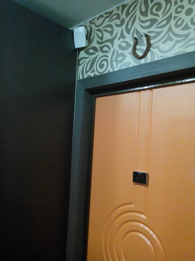
After checking, the bell housing is closed and installed in place:
You ask how we can power the assembled device. Indeed, on the line connecting the call, the voltage appears only when the button is pressed when calling. In fact, everything is simple, we will provide power to the call when the button is modified.
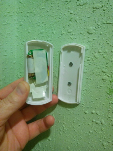
To begin with, it is desirable to de-energize the section of the circuit where we will make the modification. We take out the button from the box and connect the two standard wires together and isolate them with electrical tape. Such a connection will give us a constant supply of 220V. The current consumption, in standby mode, is tens of microamperes. Therefore, the constant inclusion will not affect the payment of electricity in any way.

Now we disassemble the transmitters and solder two wires parallel to the first buttons. We clean the resulting conclusions and connect to the contacts removed button. For greater reliability, the transmitters can be wrapped with a single layer of electrical tape.
Scheme of connecting transmitters to call buttons:

Now we install the button in place and check the operation of the call.
In the same way, we assemble the second button and fix its body on the tambour door, for example, on double-sided tape. Although I still managed to drill the wall to a shallow depth and fix it with two small screws.
Well, that's all, you can use it.
If one of the buttons stops working after a couple of years, don't panic, it's just time to replace the batteries. The transmitters are powered by 12V from a 27A element, which can be freely purchased at any supermarket. I don't think this will be a problem for sure. In this scheme, the elements have been working for a year. And since we do not often use the call, I think that they will work in this mode for at least a couple more years.
The operation of the device can be seen on the video.
The topic of our today's article is the technology of connecting an electric bell. Sooner or later you will have to install a new one or replace the old one. Oddly enough, but you may have difficulty with confusion in the wires, which, as a rule, should be 4. Next, we will tell you how to connect a doorbell in an apartment or house, attaching everything to the instructions necessary schemes and photo.
Wireless
The easiest way to connect a wireless call, because. You don't need to deal with electrical wiring to do this. Most often, the button and the main unit are powered by batteries, so all you need is to fix all the elements on the wall. The button can be put on double-sided tape or drill a small hole in the wall and drive in dowel-nails. The doorbell itself can also be mounted on the wall or simply placed on a cabinet in a suitable room. In some models of wireless devices, the buttons are battery operated, and the main unit must be plugged into a power outlet, as shown in the photo below. In this case, there should be no difficulties in connecting either.
By the way, it is recommended to install the button at a height of 1.5 meters from the floor. This height is considered the most comfortable for turning the signal on / off. As for the optimal, we talked about this in the corresponding article.
A clear advantage of the wireless model
Wired
Much more questions arise if you need to connect an electric doorbell to a 220 volt network. In this case, the actions are similar - a phase is started for a break to the button, and zero goes directly to the main block. You can clearly see the wiring of the cores in this diagram:

So, if you settled in a new building or want to install a doorbell in the house, then you need to proceed as follows:
- Choose the most suitable places to install the button and the main unit.
- Turn off the input machines on the switchboard.
- Make a hole in the wall for the cable that will connect the circuit elements. In order not to stumble upon other wires during gating, we recommend that you find out.
- From the finished hole, draw the strobes to the installation site of the button and doorbell. You can do without this stage if you conduct open wiring in.
- Fix all the elements on the walls, immediately remove the front cover so that there is access to the terminals for connecting wires.
- Connect zero directly to the main unit.
- Connect the button phase to the doorbell phase.
- Connect the phase from the bell to the appropriate terminal in the junction box.
- If the apartment has grounding and the same terminal is present in the main unit, be sure to ground the bell.
- Check the correct connection and turn on the machines on the shield. Check if the device is working.

This is how you can connect the doorbell in the apartment with your own hands. Sometimes you need to replace the device and the connection technology will be slightly different. In case of replacement, you will see that 4 wires go from the wall to the apartment. First you need to decide which wire is responsible for what. To do this, we recommend using an indicator. About that, we talked in the corresponding article
So, having rung all the cores, most likely, the picture will be as follows - on one of the cores you will find a voltage of 220 V, the others will not ring. This means that from the wall come out:
- phase from the network 220 (the indicator worked on it);
- zero from the network 220;
- wire going to the button;
- wire coming from it.
To connect a call with your own hands, you must first turn off the light in the apartment, then connect the 1st and 3rd wires. Accordingly, you must connect the second and fourth wires to the main unit, then turn on the machines on the panel and check if the circuit works.
Applied science does not stand still. Thanks to this, our life becomes comfortable and safe. So new devices and gadgets appear in everyday life, old ones are improved. They become compact, versatile and quickly get rid of wires. The same is true with doorbells. Now you won’t surprise anyone with a call with a lot of melodies, with good quality sound or imitate a human voice.
But the wireless radio call is a new product on the market. However, its popularity is growing day by day. This is due, first of all, to the fact that it is easy to install and you do not have to lay wires and drill walls. This is important when it is installed on the tambour door or on the gate of a private house.
Wireless type doorbell
So what is the secret of such a unique device. As they say, everything ingenious is simple. It is enough to look under his body to be convinced of this.
Wireless call schemes
Radio calls differ from each other in terms of features, range, or power source. They are similar in one thing - there is a receiver and a signal transmitter. A button acts as a source, and a device with a music chip, antenna and speaker acts as a receiver. Let us consider in more detail what the wireless doorbell scheme is fundamentally expressed in.
 Approximate view of the transmitter chips
 As you can see in the diagram, the transmitter consists of a generator high frequency, amplifier-converter, three transistors and power supply. A 12 volt battery is used as a power source. The signal transmission frequency to the receiver is 433 MHz. There is no antenna as such. It is two circuits that are connected in parallel. Thus, a simple microcircuit allows you to transmit a signal to 50 meters or more.
 General form receiver chips
 The receiver device is quite simple. It is based on a single transistor. From the transmitter, the signal goes to the detector. He receives it and sends it to the amplifier. The signal is then sent to the sound chip. On this chip, the future signal that a person will hear is formed. Also, thanks to him, they change melodies, choose the volume of the sound, and so on. After the signal hits the chip, it goes to the sound amplifier and then to the speaker.
Most of the Chinese-made transmitter and receiver chips are arranged according to this principle.
For comparison, consider the schemes of Chinese wired doorbells. The main difference is the presence of antennas and the way the signal is transmitted from the transmitter to the receiver.
 Scheme of a wired Chinese call
 Homemade wireless bell
Consider one of the homemade wireless analog chips similar device. Basically, they work in the same way, but there are some differences. The main difference is the frequency at which the signal is transmitted from the transmitter to the receiving device - 87.9 MHz. The device itself consists of the following main modules:
- control schemes,
- sound chip,
- transmitter,
- Power source.
Let's consider each element of the scheme in more detail.
 Scheme of a homemade doorbell radio.
 The device is controlled by the S1 button. Basically, it triggers the music chip and the transmitter's timer. When it is pressed, voltage is applied to terminals 6 and 13. There is also a chip on the resistor R2 and two diodes VD1 and VD2. It limits the upper voltage value at pins 6 and 13. This is necessary, since the USM and K561 microcircuits differ in logic level. The control device itself is used on the basis of the D1 chip. It plays the role of a timer that turns on the transmitter for a few seconds after the S1 button is pressed.
Through the elements D1.1 and D1.2, single positive pulses are generated. Their duration is directly related to the time constant in the C1-R4 circuit (taking into account the values indicated in the diagram, we can say that the duration of the pulses is about twenty seconds). The pulse changes polarity, getting to the inverter D1.3, and then goes to the key VT1. The power supply is a transformerless type, and the installed capacitor C5 dampens excess voltage.
Important! In this circuit, polar capacitors are used of an electrolytic type, C11 and C12 are ceramic, the rest are any. It is necessary that all capacitors have a voltage of at least 16V, and for C5 - at least 300V. Coils L1 and L2 are wrapped with a thin wire: 6 turns on the first, two on the second. Both of them are frameless, and the inner diameter is seven millimeters.
The UMS8-08 chip is used for the sound chip. It reproduces 8 different sounds embedded in it. The choice of melodies is carried out by turning over, by means of S1. If you start the output pulses from the D2 chip through the VT2 transistor switch to the T1 transformer with the C10 capacitor, and then to the speaker, then the signal will sound soft and pleasant to the ear (high and harsh sounds will disappear).
A piece of wire is used as an antenna. A length of no more than a meter will suffice. With such an antenna, the device transmits a signal from the transmitter to the receiver at a distance of up to one hundred meters.
Now you need to configure the device. The first step is to check the power supply. Next, check the correct operation of the sound chip. If everything works, then proceed to setting up the transmitter. For a while, the wiring closes VT1 and the emitter. The receiver itself is set at the above frequency. With the help of setting C11 and C12, we achieve confident reception at the maximum range. Thanks to the resistor R8, we set the modulation for the best sound of the receiver. Then the jumper is removed and the timer is set to D1. To do this, briefly press the button S1. In this case, the transmitting device turns on and works for a few seconds. If this time interval is too small or, conversely, too large, then it is changed by selecting R4 and C1.
Thus, having minimal knowledge and purchasing everything you need at the nearest radio store, you can make a reliable call with your own hands.
Call from unnecessary devices
If you have old phone or broken computer mouse and their repair is impractical, they will come in handy if you decide to make your own wireless doorbell. Consider the option of manufacturing such a device from a mouse:
- All the insides are removed from the case except for the contact buttons.
- On the board, two keys are connected to the ringing device, and the remaining parts are removed.
- The wheel is cut in half and one part is glued back.
- On the remote control board, it is soldered to the sound button twisted pair. It connects a button to the mouse buttons.
- We solder the remaining ends to the contacts of the keys - one to the extreme, the second to any of the remaining two.
- The last contact of the three is connected by a wire to the opposite one. This way both buttons will work.
The original call is ready.
In contact with
Comments
Vladimir 28.03.2017 21:44
Cheap angrily effective. Need to be armed!
Grade
New Articles
New comments
ArtemGrade
ElenaGrade
nezabudka-1Grade
CatherineGrade
VladimirGrade
adminadmin