Introduction
The shape of the future body was based on the cube shape, hackneyed in other mods. However, some restrictions were introduced, namely the minimum possible sizes. Considering that the maximum (height) of the side motherboard was equal to 32cm, then the internal volume should be 32x32x32cm. The second condition of the mod was to create it from the simplest and most accessible material, the processing of which does not require high-tech and expensive processes (laser cutting, airbrushing, etc.). At the beginning, I wanted to create a cube from solid natural wood 16-20mm thick, which can be bought in construction stores, but however, in the nearest store the price turned out to be quite high - 300-350 rubles per 1 m2. The choice fell on... plywood. Yes, ordinary plywood 10 mm thick. According to calculations, a quite affordable sheet of 1500x750 mm came out for about 150 rubles. In order to hide from the sides of the mod all the fastenings, errors and alterations on top of the inner body, it was decided to make decorative panels from 5mm plywood.
In principle, the entire fashion process is clear from photographs. But let me make some clarifications:
Fig.1-3. Round cables from the power supply. I decided not to use standard Molexes, but used 4-pin round connectors purchased from Micronika. The shower hose is attached to the Molex with a staple made from a paper clip, and the connector itself is screwed into the plastic seal of the same shower.
Fig.4. Placing components in the power supply bay. The power supply is placed upside down under motherboard. The air passing through the power supply is blown into the bottom of the cube by a 120mm fan. A cheap compressor also found a place in the power supply, but I did not decide to experiment with connecting it to the general power supply and simply removed its cable from the case, giving me the opportunity to turn it off if necessary.
Fig.5. One of the IDE power cables was not unplugged and moved to a connector, so it, along with the motherboard power cables, comes out of the power supply. Below them are the device power sockets and the glued-in water block power connector (+3V removed from SATA).

Fig.6. rear wall with cut-out holes for the motherboard and expansion cards. In the center of the power supply comes a socket for a 220V power cable. Two grilles from old cheap speakers turned into a protective mesh.

Rice. 7. Illuminated case fans are protected not only by a handle for carrying the cube, but also by a metal mesh (purchased from IKEA). The mesh is located between the inner body and decor panels.
Rice. 8. The hinged cover block houses DVD and CD-RW. The IDE cable passed through the bottom wall of this block so that it remained in the case. On the other side, a Molex connector is embedded into the wall, from which power is already supplied. There is also an LPT connector for an LCD screen built into the back wall.
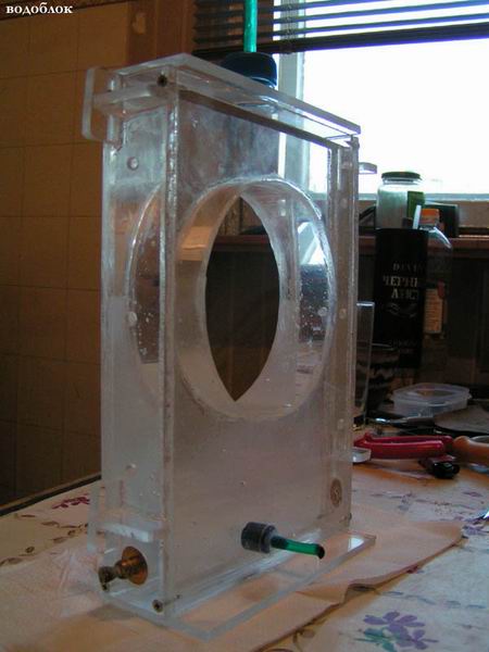
Rice. 9. Water block for bubble mod. To fill the water, a neck cut from a plastic bottle is cut into the upper wall. Since there was a water cooling device in the future, brass tubes were glued into the milled holes in the lower part to hold the shower hose (fitting?). An aquarium sprayer was glued into the rear part from the bottom - it gives more bubbles than just perforating the tubes. A panel with the necessary buttons and switches will be attached close to the large through hole on the inside. Six UV diodes are responsible for illuminating the water block.

Rice. 10. Front panel. Rear view :) It has: reset and power buttons, two switches for backlighting the water block, two USB port, 3 variable fan control resistors and 10 diode HDD operation indicator. Since the POWER, RESET and HDD LED contacts on the motherboard are already grouped together, using a multi-core wire and a USB connector managed to reduce the number of wires to a minimum.
Figure 11. The actual internal layout. Part of the air blown into the case by the right fan is taken by the processor turbine cooler. The hard drive is hidden under the wires on the left wall.
Fig. 12. The case is switched on without the front decorative panel.

Fig. 13. The work of bubbles in a water block
Fig. 14. Housing without decorative panel in night mode.
Fig. 15. Front decor panel with holes for DVD-CD-RW and water block. To highlight the contour in the lower part, the cut out part is glued to a metal mesh with super glue. I also immediately cut out the stealth panels for DVD and CD-RW.
Final photos of the body
Fig. 16 – night building
Fig. 17 – daytime
Fig. 19 - DVD tray with attached stealth panel.
Fig.20 – front panel.
Anton aka =SNAKE=
antogor (a) pochta.ru
25
/10.2005
For a computer in a store. They can be horizontal or vertical - this is the most common type. However, if you do not take into account some variation in the front panel, they all look the same, differing only in color. A boring metal box with a couple of buttons and a couple of LEDs may not satisfy the sense of beauty, and then you want to make a case for your PC with your own hands. There is another situation - the existing one is no longer suitable in terms of functionality - there is not enough space in it or there is insufficient ventilation, causing the computer components to overheat. For example, sometimes you need to add a second video card or several hard drives, and a standard case becomes unsuitable for all this. There are other situations when you have to make a computer case yourself. For example, all the money is spent on top-end components, but there is not enough budget for the body. Or you have a laptop with a faulty display, and you want to turn it into a desktop one. The cases are different, but they have one thing in common - you need to pick up the tools and make a computer case with your own hands.
Making your own PC case.
What you need to consider
The most important requirement for any computer case, including a homemade one, is sufficient space for ventilation and cooling. It is no coincidence that in the standard, most common Moddle-Tower Form cases there is a lot of empty space. This allows air to circulate freely, and when installing energy-intensive components, it is possible to add additional fans. Therefore, when developing a home-made design, it is necessary to take into account not only the dimensions of all components, but also provide free place for air circulation around each of them. You also need to decide how the power supply will be installed. There are two options:
- Above. This classic scheme, in which warm air flows out through the power supply. This ensures ventilation and reduces noise levels. But there is also a minus - the power supply itself may overheat if there are no other coolers. The circuit diagram of a system case with a top-mounted power supply is usually used to create it yourself.
- From below. In this case, the power supply is placed on the bottom of the case, and air enters it from below, through the grille, and is blown out through another wall. Plus - the power supply is well cooled exclusively by “outside air”. The downside is that it does not participate at all in the cooling system of the system as a whole, so coolers are definitely needed. Another disadvantage is that the air flow to the power supply occurs under the bottom of the case and can be difficult. In addition, the noise level will be increased - it is created by the movement of air below, plus the noise from the fan is transmitted directly to the surface.
If you choose the horizontal option - the Desktop type, then the requirements remain the same, except that there is less room for maneuvers with the power supply. However, ventilation must be provided for all units.

Which material to choose
A homemade computer case should not only be beautiful, but also durable and functional. Although some even make it from cardboard boxes, this is not at all serious. Usually the following materials are chosen:
- Tree.
- Plexiglas.
- Aluminum.
- Steel.
Each option has its advantages and disadvantages. Let's take a closer look at them.

Plexiglas is easy to saw and cut; with proper care, the body turns out to be quite professional. This option is usually chosen by modding enthusiasts - creators of beautiful and original transparent cases with many lights inside. Among the disadvantages is that this material still requires the ability to handle it and skills in processing it. An awkward movement and a long, deep scratch is guaranteed.
Aluminum has a lot of advantages, the main ones being that it is lightweight and has good heat transfer. However, this is a relatively expensive material, and due to the flexibility of aluminum, the rigidity of the body and internal partitions will be rather weak. And it scratches easily, so surface treatment is required. Steel perfectly damps vibrations, has good thermal conductivity, and is durable. The steel case will reliably protect the internal components from any influences. But processing steel requires different tools, and this work is not easy. But the result is excellent.

Before you make your own computer case, the issue of material must be resolved. If you don’t have the skills to work with metal, but you want to use it, you can do this - design all the patterns and make drawings. In many cities there are workshops and enterprises where, according to custom drawings, they will accurately cut out and even deliver all the parts from the metal of the required thickness. All that remains is to assemble this constructor. You can do the same with wooden blanks.
Case design
It’s difficult to give any advice here - everything is strictly individual. You can make a case with a standard design only out of necessity, when you don’t have the money to buy it, although it doesn’t cost that much. Therefore, creative people usually take on this work in order to do something original that no one else has. Or to solve some technical problem - for example, placing the contents of a laptop in a separate case and securing it behind the TV. Fans of modding - experiments with the design of a computer case - have created all sorts of options. These are wall-mounted options, including in the form of a panel under glass. These include numerous transparent cases with spectacular lighting of coolers and other components.
Some even made it out of a glass-topped tabletop. Shapes can also be different - from classic parallelepipeds to spherical or pyramidal. There are also more complex ones - in the form of some characters, for example, the robot R2-D2 from Star Wars. Cases made in retro style look good. For example, a model stylized as a lamp is effective. Soviet equipment, with many dials and knobs on the front panel - by the way, they function and show processor load, memory, and other parameters. Futuristic and post-apocalyptic designs are also popular. Many computers are designed in the style of the game Fallout.
A DIY PC case always has a personal design because it exists in a single copy. However, before you take on this creative endeavor, do not forget to calculate and provide all the technical aspects that were discussed at the beginning of the article. No matter how your computer case looks externally, comfortable working conditions should be created for the internal devices even under maximum load.
In the age of computer technology, it is impossible to imagine life without a computer or any other multimedia gadget. Those who understand computer hardware assemble their own computers, giving them certain characteristics that they need to complete their tasks. Some modify their computers, so to speak, in their original shirts, and some go further and manufacture system units in various variations. So the author decided to independently upgrade his system unit, giving it an exclusive, attractive and creative look.
For the base of the system unit, the author used a wooden rounded square. This can be found in subwoofers. They are naturally longer, but if you have a hacksaw or an attachment for an angle grinder, reducing it to the size you need will not be difficult.
the next step is to make a groove around the entire perimeter of the workpiece into which the wall will fit system unit. For this you will need a chisel and a hammer. If the farm has a milling cutter, then things will go even faster, and the result will be much better.


Next, in the upper part of the workpiece, we begin to cut out an opening for two fans using an electric jigsaw. If you have more quantity and space, you can install more. It won't hurt. The location of the future cut is marked and either electrical tape or masking tape is placed along the edge of the cut. This is to prevent chips and burrs on the surface. Drill a hole for the jigsaw blade and cut it out. We insert the fans and see how they are located. If everything suits you, then good. If not, we bring it to mind - polish it and so on. For further work it is necessary to remove them and put them aside for a while, because They will interfere with you when carrying out other work.

Next, we determine where and in what order the remaining connectors will be located - USB, space for hard drive and so on. Everything is cut out in the same way as described above.

One of the walls of the system unit is installed.

Next, all components are installed. They fasten everything with small wood screws.

The metal wall is attached to the base and fixed. From the inside they are also attached to the corners.


Now a hole is drilled in the wall for the power button.

We assemble and fasten the strips on which all the connectors are located.

Next we make the legs. They are cut from the same material that you use to build the body. Glue them to the bottom and wait for them to dry. For a more durable connection, you can drill through holes in the legs and not through holes in the body. And put it all on self-tapping screws.

connect the power button and install the wall in place.

The author made the second wall from dark transparent plastic. Placed around the perimeter LED strip. When you turn on the computer, it lights up and all the insides are visible. Quite beautiful and unusual. When turned off, the system unit has a strict appearance.
Good afternoon, Khabrovsk residents. Thank you very much for the invite! And although it’s not a good idea to start by translating other people’s posts, perhaps someone else will find this homemade project mega-cool.
This is a translation of a post from the Overclock.net forum. User Show4Pro decided to take out all the insides of his super computer and hang everything on the wall. Great idea perfectly executed. For those who are interested in how it was assembled and how it works - welcome to the cat.
The last time I updated my home machine was 1.5 years ago. Well, I thought about upgrading the car to i7 (before that there was Bloomfield), although in fact, more powerful processor I didn't need it. I wanted to buy a new case - Corsair 900D, to replace the 8 year old Super Armor. But I wanted something special, unique. In Battlestations on Reddit, I came across a very simple but elegant solution - a wall computer. And that's where the whole project began.
Accessories:
CPU: Intel Core i7 950
Motherboard: Asus Rampage III Extreme
Video cards: 2 x AMD HD7970
RAM: 6 x 2GB Corsair Dominator
SSD drives: 4 x 120GB Corsair Force GT SSD
HDD drives: 2 x 1TB WD Caviar Black
2TB WD Caviar Green
1.5TB WD Caviar Green
Power supply: Corsair AX1200i
Sound: Creative Sound Blaster Zx
Cooling:
Cooling for CPU:
CPU Water Cooling Radiator EK Supreme HF Full Copper
Pump Swiftech MCP655 /w Speed Control
The cooler itself FrozenQ Liquid Fusion V Series 400 ml Reservoir - Blood Red
XSPC RX360 Performance Triple 120mm Radiator
GPU cooling
Heatsink for video card EK FC7970 - Acetal+EN
The pump and cooler are the same as for the processor.
Swiftech MCP655/w Speed Control
FrozenQ Liquid Fusion V Series 400 ml Reservoir - Blood Red
Water cooling radiator Watercool MO-RA3 9x120 LT Radiator
Other:
Cooling system pipes
Koolance QD4 Quick Discounnect No-Spill Coupling
Bitspower G1/4 Silver Triple Rotary 90deg Compression Fittings
Monsoon Free Center Compression Fittings
Phobya Angled Clip 90° Tubing Guide
Phobya Terminal Strip Tubing Clip/Holder
The cooling tubes themselves (red) PrimoChill Advanced LRT Tubing Bloodshed Red
Phosphorizing refrigerant, blue color EK UV Blue Non-Conductive Fluid
Cables:
Bitfenix Alchemy Premium Sleeved Extensions
Corsair Individually Sleeved Modular Cables
Creation.
To start, I took photos of all the components in their actual sizes and put it all together in Photoshop. This way I was able to move them around the work surface and decide what it would look like. Well, this is necessary for routing the cooling pipes. Here are a couple of layouts:
I abandoned this due to the empty space in the lower right corner. And the motherboard ended up on the left, although it should be in the very center and attract attention to the entire panel. 
There is also a lot of space on the right, although the power supply and motherboard are closer to the center. In the final version, the cooling tubes stretch along the entire right edge, plus two thermometers appeared there.

I transfer the drawing of the motherboard onto an acrylic sheet.

Since the video adapters will be far from the motherboard, I ordered PCIe slot extenders for each of the cards on eBay. This is me testing how they work. However, later I had huge problems with the cross-function of the cards due to cheap unshielded wires. They ended up on top of each other and created serious interference. The system was stuck loading the BIOS. It was possible to launch it with only one card. In the end, I had to shell out for very expensive cables with good protection. But more on that later.

The goods have arrived!

Most of the water cooling is from Performance-PC. They even gave me a T-shirt and two mouse pads!

Acrylic backing for motherboard.

All acrylic panels are cut at 45° to achieve a glowing edge effect.

The holes are drilled and the fasteners are installed.
TA-dah!!! It turns out that the mother of Rampage III Extreme is eATX format. And this is for the ATX form factor.
I made the correct eATX substrate later.

Time to gut my old dusty case.


In the old computer, the disks are inserted into Vantec HDCS boxes, which make 3 HDD boxes out of 2 5.25" ones.


Video cards.

Supports for all components.

Custom acrylic pump mounts.

Close-up of rough trim done with a table saw. They will need to be sanded later.

There is a triangular cut in the center of each plate. It will reflect light that is projected perpendicularly inside the plate at the edges. Without a cut, the edges barely glow.


Test with the light on on the sound panel.

All panels are sanded with 120 grit wet sandpaper.

Close-up of sanding.
All back panels are pre-drilled.

Under the table is acrylic snow.

Preparing to paint red.
Surprisingly, Corsair included thermal pads on the blades, although they don't get hot at all.

Marking all components on the main board to mark various slots and holes. Board - 1/4" 48 x 30 fiberboard.

All cracks and holes are marked in their places.

I'm getting ready to cut out the slots with a jigsaw.


I glue the frame.


I paint the inner edges black - to match the color of the carbon film.


Soldering LED strips.

Workplace.


LED strips. Temporary fastening.

I glue a giant vinyl film. This was the cruelest part. I almost had a heart attack. How to stick a film on a phone screen, only x1000 more.

No bubbles!


I use aluminum tape to hide the LED on the front side of the panel for hard drives, between them.

My assistant is Tommy.

All substrates are installed in their places on the common board using #10 screws. I screwed them into pre-prepared holes.


Checking the light.

Coolant and cables have arrived. I used Bitfenix for the components and Corsair for the power supply.


On the left is Bitfenix, on the right is Corsair. Bitfenix doesn't have black heat shrink on the ends, so the Corsair looks cooler.

Red zip ties to tie up hanging wires.

Backside. All cables are connected.

We test for leaks while the entire system is lying on the floor - this makes it easier to troubleshoot problems.
First start.
Not loaded. I connected via iROG USB to the laptop to view the download log. It turned out that the system was stuck on the VGA BIOS. I disabled one of the video cards - everything worked. I tried to connect another one - it also works. Both cards are not. Did some research and found that unshielded PCIe extenders with ribbon cables are very susceptible to EMI. I tried to shield them by wrapping them in several layers of aluminum foil. 

After 4 layers of foil I was able to get both cards running. But the machine immediately froze as soon as I launched any game or any 3D editor. Moreover, my Soundblaster is also cascaded with a cable to the 3 x1 PCIe slot, and this also greatly interfered with the operation of the video and hung up the system.
As a result, with pain in my heart, I had to order expensive protected extenders for PCIe slots from 3M (approx. $100 each)

Shielded 3M extension cords in place. They turned out to be longer than the previous ones and now both video cards have reached PCIe x16.


Changed the previous sound to SoundBlaster Zx. This one looks amazing!

And finally
On this moment everything works smoothly. The installation has only 2 fans. On the PSU it barely moves, and I installed another one on the chipset - it’s very quiet. The pump runs at the lowest power, so the computer came out quite quiet. The only annoying thing is that it turns out that you can hear the operation of some components outside the case. In my case, this is the buzzing of the video card and 1TV hard drive.EK UV refrigerant is very sensitive to ultraviolet radiation. I know you shouldn't mix coolants to preserve their properties, but damn if I used it undiluted, I wouldn't be able to see the coils in the reservoir. For both circuits I used about 1/8 of the jar, the rest was distilled water.
From the translator
I in no way claim any authorship of this incredible project. It’s just that I’m a journalist with a degree in electronics engineering, and doing such things is my dream. And to be honest, I would make a table, not a wall. So I decided, suddenly not all Khabrovsk residents are sitting on...actually it all started many years ago, around 78, when I was four years old... When visiting relatives, they took out a large iron box with tools, light bulbs, switches and similar “trash”, after which throughout the entire “visit” I was neither seen nor heard. By the way, the owner of that box, my uncle, is very straight arms...
Currently, I work as a carpentry foreman. I have been craving for everything that contains microcircuits for a long period of time, but from the moment I purchased my first computer, the thoughts of “doing something with it” systematically appeared in my head. Then I found out what it was modding... And from that moment there is not a day without thinking about it... By the way, this is my first job...
That's probably enough introduction, let's get straight to the point. Every mod I make starts with a lot of thinking about what I want to do. As a rule, I don’t make drawings (but in vain :)), many thoughts come while doing the work. Unfortunately, at the time the mod started, I didn’t think that I would show my work somewhere (on the Internet), so there aren’t very many photos... Well, let’s begin...
Of course, it all started with a search for the system unit case; a damaged case of unknown origin was purchased, which served as the basis of the system unit. The idea was to make a wooden case and, moreover, it would not be embarrassing to show to friends, but since this is my first work, I decided to focus on the classic layout. The hardware was bought all new, here is a list of what was used
CPU Core 2 Duo E8400, 3000 MHz (9 x 333)
Motherboard Asus Maximus Formula
Memory OCZ XTC SLI OCZ2N800SR2G * 2 pcs
Video ATI Radeon HD 3870 (RV670)
Sound adapter Analog Devices AD1988B @ Intel 82801IB ICH9
Sound adapter C-Media CMI8738/C3DX Audio Device
Disk drive ST3500320AS ATA Device (500 GB, 7200 RPM, SATA-II) * 2 pcs
Optical drive TSSTcorp CDDVDW SH-S202H ATA Device
power unit CHIEFTEC CFT-500-A12S
CPU cooler Noctua NH1-U12P
Fans Thermal Take Cyclo Blue Pattern A2450 * 2pcs
I don't count the numerous LEDs, neon lights, wires, etc. The tools used were those that are available in any carpentry workshop... Unfortunately, I don’t have a Dremel... For now...
Actually, I started by re-gluing the front panel, base and cover of the system unit. The most important thing in carpentry is not to forget the golden rule. measure seven times, then measure again and only then cut, so we’ll cut off all the excess later.
Here is a photo of the future front panel:

I'll make a little clarification. For the top cover and front panel, I re-glued oak panels and drove them to a thickness of about 17-22mm, then glued the slats along the edges. I made markings on the front panel, placing them against the iron frame of the system unit, after which a hole was made for the 120th fan using a ballet dancer and a hand jigsaw. Next we make the side walls from plywood.


On the following photos you can see how the side wall will open. Plus - when you remove the wall it opens good access to all internal components system unit, minus – In order to open it completely, you need to move the case away from the wall... Fortunately, you don’t have to open it often...


When the blanks are ready, the fitting of all the parts of the future body to each other begins. And also finishing all sorts of little things...

Subsequently, you should receive a practically assembled body, ready for further processing (grinding, painting)


After some time (there was a lot of work) I began adjusting the body frame. The thing is that the fans didn't fit in, so I had to cut it a little. Well, since I don’t have a Dremel, we use a grinder (don’t forget about Safety precautions)

And cutting off everything that bothered us

Let's start preparing the frame for painting. Due to limited funds, it was decided to limit ourselves to sanding and painting itself...

While the first layer of paint on the side wall is drying, cut out the window (jigsaw, hands) and place the pre-cut glass for gluing

Of course, the painting process takes a lot of time, the intermediate layers need to be sanded (500-600 sandpaper), painted again, etc. and so on. As a result, we get a frame ready for assembly.

But not all parts of the body are ready for assembly, so we are painting the “wooden component”


By unknown reason The painting process itself was not photographed, but I can say that everything was painted with DUFA paint. It was opened 4 times with sanding between layers (grit sandpaper 600-800), then it was opened with varnish 2 times... let's start assembling... The photo is also why- then they weren’t done, I can only note that the assembly took place over the course of 2 months (the motherboard was missing, I was waiting for it to be delivered) While I was in “standby mode” I started working on the power supply.
I inserted blue LEDs, cut out a side window, connected a 7 volt fan... In general, standard procedures aimed at “improving appearance and operational properties" of this device. The fans in the case are also connected to 7 volts (front) and 5 volts (rear). The USB compartment cover is illuminated, and the computer's power button is also located here.

This made it possible not to place the power button directly on the front panel. The DVD-ROM tray is also illuminated and instead of the opening button there is a reed switch (located right behind the stickers that were later removed :))

And finally, the final photos


I’m currently hatching plans in my head to build a case based on the Core i7. And, of course, I hope this is not my last article, I’ve also made a test power supply and a mouse (more like testing the veneer technology).
Did: Mikhail Kopylov