The circuit is a fairly simple analog pinpointer for people who are searching for coins, but cannot afford to buy a professional pinpointer. I personally collected this sample and confirm its full performance. I built a printed circuit board specially for him, which can be found at the end of the article. According to the characteristics of the pinpointer, it’s not bad enough, for target designation of the find, that’s it ....
Scheme of pinpointer MINIMAX-PP-2

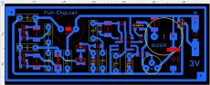
according to the scheme, I think there will be no questions, on printed circuit board all elements are signed, please note some details on the board do not match the diagram, since I bred it to match what was in the local radio store !!!
All capacitors that are used in the generator must be film capacitors with an operating voltage of at least 100 volts.
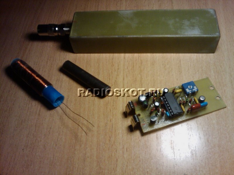
Regarding the L1 loop coil, I wound it on a piece of a ferrite rod with a diameter of 10 mm. from the magnetic antenna of an old radio. The length of the rod is 10 cm. I wound the coil in 4 layers with an enameled wire with a diameter of 0.35 mm. the number of turns is 450. after winding, I soaked the coil with zaponlak and crimped it with a heat shrink tube from above.
According to the printed circuit board, it is one-sided using both dip and smd components, the buzzer is not just a speaker, but a speaker with a generator!
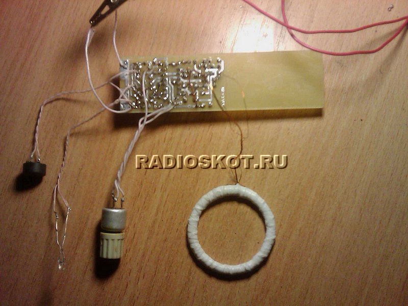
And finally, a few photos of the assembled board.


I will post soon short video with the operation of this pinpointer
Download schematic and PCB file
They are quite different. It should also be noted that devices of this type has its own sensitivity. The main element of the pinpointer can safely be called a coil. It is installed most often of an orthogonal type. However, in this situation, much depends on the accuracy class of the device. In order to assemble a simple pinpointer with your own hands, you need to familiarize yourself with the known configurations.
Two-wire capacitor model
To make this type of pinpointer with your own hands, you must first prepare a case for the device. To do this, many experts recommend using a regular flashlight. The main problem on this stage is to find a good modulator. As a rule, a non-linear analogue is selected for a two-wire capacitor. The coil itself must be located in front of the device. Batteries should be installed behind the modulator. You can also take them out of the flashlight. The minimum battery capacity must be 200 mAh. For 25 minutes of continuous work, this is enough.
Using three-wire capacitors
Making a do-it-yourself pinpointer with three-wire capacitors is quite difficult. The modulator in this case is only suitable for a linear type. Nowadays, it is not easy to find it in radio electronics stores. It should also be borne in mind that the coil must be installed under the amplifier. Some additionally equip the devices with zener diodes. To increase the sensitivity of the model, they are ideal. Batteries in this situation can be used as standard from a flashlight.

Model with signal interruption
To assemble this type of pinpointer with your own hands, you must first take the case from the flashlight. At least the modulator must withstand the threshold frequency of 200 Hz. All this will allow the sensitivity of the device to be maintained at high level. As a tester, this device is used quite often. To activate the interrupt mode, a regulator must be installed in the design.
Most often it is used button type. In this case, it is necessary to pay attention to the features of the case that belonged to the flashlight. It is better to choose a simple coil for this purpose. However, it must withstand the input limit voltage at a level of 15 V. All this will improve the accuracy of the readings.
Modification "Kid-FM2"
Assembling the pinpointer "Malysh-FM2" with your own hands is quite simple. This device differs in that its sensitivity is low. However, the cost of the model is extremely low, and this device is ideal for home use. The modulator in this case is of a non-linear type. It is mounted directly next to the regulator.
Most often on the market you can find exactly rotary analogues. The inductor input threshold voltage can withstand a maximum of 10 V. It should also be noted that for this device high current conductivity. This was achieved by installing a zener diode. Next, to assemble the pinpointer with your own hands "Kid-FM", you need to solder the capacitors. Only after that the contacts are connected to the zener diode. At the end of the work, it remains only to fix rechargeable batteries in the hull.

Pinpointer on transistors of low sensitivity
You can make a low-sensitivity pinpointer with your own hands on transistors thanks to a device such as a beeper. It is installed in the housing immediately behind the modulator. The amplifier for this device is only suitable for a pulse type. In this case, the capacitors for the device can be selected different. However, they must withstand a minimum input threshold voltage of 5 V.
It should also be noted that zener diodes are installed in devices quite often. Their limiting frequency is welcomed at the level of 200 Hz. It is important to take into account that the accuracy of the readings depends on the bandwidth of this element, most often does not exceed 3 microns. Batteries for the model are selected with a capacity of not more than 600 mAh. This is approximately enough for the device to work continuously for 30 minutes.
High sensitivity model
High sensitivity how to make a do-it-yourself pinpointer? To understand this issue, it should be understood that the coil will be required for assembly is quite powerful. It must withstand a minimum threshold voltage of 20 V. It should also be noted that modulators in this case are only suitable for a linear type. The accuracy of the readings also depends on the type of condensate.
In this situation, many experts advise using open-type models. On average, the capacitance parameter for these elements fluctuates around 5 pF. However, in this situation, a lot depends on the manufacturer of the capacitors. If we talk about the zener diode, then it is used with increased resistance. This is necessary to increase the sensitivity of the device. Batteries for this model should be selected with a capacity of at least 900 mAh.
Modification Minimax-PP
To assemble a Minimax-PP pinpointer with your own hands, you need to choose a beeper of the PP20 series. It should also be noted that vibration mechanisms are installed in devices of this type. In this case, the indicators are used in a variety of ways. If we talk about the coil, then in this case it is used of an orthogonal type. Threshold input voltage this component must withstand at least 15 V. In this case, the resistance in the circuit must not exceed 4 ohms.
The sensitivity of this device is largely dependent on the capacitors. In total, there are two of them in the standard scheme. One of them must be installed near the coil. In this case, the second one is attached at the output on the modulator. The main problem of these devices can be considered a small bandwidth at the level of 2 microns. Due to this, amplifiers are rarely used in devices of this type.

Integral controller device
Assembling this type of pinpointer with your own hands (the diagram is shown below) is quite simple. First of all, you need to choose a good case for the device. At the same time, the integral type controller does not take up much space. If desired, it can be purchased at any store with radio equipment, and it costs very little. Distinctive feature this element can be safely called good conductivity. Capacitors in this case are installed two-electrode type. Their resistance parameter fluctuates on average around 2 ohms.
It should also be noted that the coil must be installed first. To do this, you will have to use a blowtorch. Next, the modulator is attached directly. In this case, the batteries must be located in the rear. The amplifier in this case is not practical to use. This is due to the fact that the sensitivity of the device is significantly reduced due to an increase in the limiting frequency of the device.

Use of multilayer capacitors
A do-it-yourself pinpointer is assembled with multilayer capacitors (the diagram is shown below) only in the presence of orthogonal coils. Modulators in this case are suitable for linear and non-linear types. It should also be borne in mind that vibration mechanisms are often installed in devices of this type. At the same time, beepers can be found quite often.
Zener diodes are often used to increase the sensitivity of the device. At the same time, cardioid analogues are especially popular in our time. To install them, you will have to use it. In general, it should be noted that models with multilayer capacitors are universal, and are ideal for home use. With their help, a person is able to quickly find out the exact location of the wiring in the wall.

Model on a monolithic board
Assembling this type of pinpointer with your own hands is quite simple. These devices differ not only in increased accuracy of readings, but also in good sensitivity. For professionals, this model will fit well. It is necessary to assemble the device from fixing the modulator. In this case, many experts recommend using linear analogues.

However, non-linear modifications are also common. Beepers in this case are installed behind the coil. The input threshold voltage parameter of the device should not exceed 20 V. For this purpose, zener diodes are installed without fail. The regulators in this case are soldered at will. At the end of the work, it remains only to fix the batteries.
Pinpointer with resonant regulator
To fold the device with a resonant regulator, you must prepare a blowtorch in advance. First of all, the device is selected quality modulator. Many experts in this situation still recommend the use of linear analogues. Finding them in the store is quite difficult, but they should cost little. On average, their conductivity parameter is 3 microns. Due to this, the input threshold voltage can be expected to be at the level of 15 V. Zener diodes for the device are suitable for a wide variety. They must keep the maximum resistance at 5 ohms. It should also be noted that a device with regulators does not need beepers.
In this case, it is advisable to install the coil last. In this case, the insulation of the wiring must be given Special attention. It should also be remembered that the case of the device must be completely sealed. For this purpose, as an option, you can use a rubber seal. The regulator should be soldered directly to the modulator. Capacitors in this situation are mainly used in the field type. The minimum battery capacity must be 800 mAh.
Simple reliable pinpointer
17 January 2017
This diagram shows a simple metal detector, such as a pinpointer. The circuit is not complicated, after assembly it works almost immediately. Requires minimal adjustment: the resistor R1 sets a voltage of about 2.5V on the 7th leg of the LM324, this voltage must be selected after each change of the sensor.
After a target is detected, auto-tuning reduces the sensitivity of the detector and after a while the sound and light alarms stop. If the target approaches the coil again, the alarm is resumed, this will continue until the automatic control fails, after which the alarm will not turn off until the target is at such a distance from the coil at which the auto-tuning will not resume its work again.
With a change in temperature, and in connection with this, a change in the parameters of the circuit elements, Feedback compensates for the change in voltage on the generator and the operation of the circuit is not disturbed and does not require any manual adjustment.
If you put the elements R14, R15 indicated in the diagram by a dashed line, then you can additionally adjust the sensitivity threshold in manual mode.
In the diagram in the generator, the resistance value - R3 "(680 Ohm) is given for a coil on a 50 mm ferrite rod, 8 mm in diameter, which contains 320 turns of 0.3 wire. if there is another coil, the generator will not start. Therefore, it will have to be reduced before a stable generation, or use the following refinement option:
Scheme modification option. To reduce sensitivity and also make it easier to run the master oscillator (oscillator circled in red) with different coils, you can change the following:
- Replace R3" in the alternator with a jumper
- R3 use 430 ohm
The sensitivity will noticeably decrease - the influence will decrease magnetic field earth, with sudden movements of the coil around its axis, the signal will not work. During the tests, many noted that this decision most successfully.
In the version with a jumper instead of R "and R3 \u003d 430 Ohm, the device works with any coils if they ensure the operation of the generator at frequencies from 15 kHz to 20 kHz. One of the sensor options according to this scheme is 60 turns 0.5 on a 7 cm mandrel. With a coil 19 cm is definitely not for coins - with such a coil for coins, its sensitivity is weak (frequencies up to 20 kHz were tested).
One of the design options for the coil connector is shown in the figure below:

Instead of KP303A in this circuit, you can use - BF245, 2N4416, 2N5457. Recommended BF245. Transistors 303E, 303D, 303G are not recommended.
The value of R1 may not be enough to set zero on U1D.
As a speaker, you need to use a high-resistance piezo emitter, the volume and brightness are selected by resistor R9. You can also use a regular tweeter, but the consumption of the whole circuit will increase.
If the sensor reacts to touching the ground, it is recommended to make a screen on the coil.
By setting: If it reacts only to pieces of iron and does not see a non-ferrous metal point-blank, then the generator may not have started. Check if there is a sinusoid on the generator coil? If not, then an EMF is simply induced in the coil from magnetized pieces of iron moving in front of it. In this case, there should be no reaction at all to non-ferrous metals.
If you do not install the LED will not current K-E Therefore, the transistor will not work.
If it does not work at low temperatures, you can add a 470nF capacitor between R2 and the second terminal of U1A, remove R10 (gap), R14 use 300kΩ.
Schematic diagram of a homemade pinpointer:

The circuit was tested with a ferite rod 8 mm in diameter, 50 mm long, 320 turns of 0.3 wire. Ring with a diameter of 40 mm wire 0.14 - 150 turns. The ground test was carried out with a ring coil. With sudden movements or rotation of the coil around its axis, it reacts to the magnetic field of the earth, but this is not particularly annoying, since the search is carried out with smooth movements and without rotational movements.

A flat coil can be made from a fiberglass plate cleaned of copper.
The integral stabilizer 78L05 can be replaced with a similar one with an output voltage of 5 volts. If you do not need a VCO (voltage controlled generator), then the resistor R16 must be reconnected to the 12th leg of U1B - shown by a dashed line.

You can replace the transistors of the KT3102 pinpointer with any low-power silicon ones, you can use another sound emitter with a voice coil resistance of at least 100 ohms, but it’s better to put a piezo - it will be economical and loud enough. LED - any super-bright.

This pinpointer is powered by a 9-volt "KRONA" battery. On the printed circuit board of the pinpointer, places are left for soldering current collector springs for connection to the battery. There is also room for a flat coil on the board. Coils in this case can be of any design.
Capacitors C2 and C3 must be film or others but with zero TKE, the rest of the capacitors can be of any type.
The "threshold" regulator can be omitted, but with it you can increase the sensitivity and also decrease it when necessary. So I recommend not to remove it. The sensitivity of the pinpointer is very high, a small gold ring starts to feel with manual adjustment from 7 cm.

Here is an archive with LAY format, when you hover over an element, the position of the element is displayed. Material sent - Slavake.
Discuss the article PINPOINTER