A very common cause of failure personal computer is the failure of the power supply. The main symptom will be the fact that your computer won't turn on.
In order to confirm the failure of this part of the computer, you need to test the power supply. Let's consider several methods for such a check (they are no more difficult than the methods for checking RAM).
The main function of the power supply is to convert the incoming voltage to the required value.
Checking with a paperclip
The easiest way to check the power supply is to use a regular paper clip. As part of this method, we will try to turn on the power supply without a computer and check if it works.
To do this, you will need a paper clip, a power supply and a device for the load. After disconnecting the computer from the network, you must remove the power supply. As a load, you can use a standard 80-mm cooler or an optical drive. (if there is one in the system unit). It is also possible to use them together.
We connect the power supply and in the largest 24-pin connector we look for a contact with a green and black wire. There is more than one black wire, so you can use any. Usually use the contact that is nearby.

The closure must be done short. If the power supply is still working, then the fan of the power supply itself, as well as the 80-mm one, will begin to rotate. The connected drive will signal with a green light. If none of this happened, then the power supply is faulty.
visual inspection
If the warranty period of the power supply has already expired, you can carry out an internal visual inspection, which can clearly confirm the malfunction of this device. Before starting disassembly, be sure to disconnect the power supply from the mains! After removing the cover, you can see the following picture:
In this case, no additional devices are needed to determine the fault. In the last hours of operation of such a PSU, you could hear the smell of burning. Overheating and subsequent failure can also be caused by a malfunction of the cooling system. As a rule, this is a characteristic disease of cheap Chinese power supplies.
The presence of one or more "swollen" capacitors will also confirm a malfunction. But not always replacing them can restore performance. It is necessary to pay attention during such an inspection to the protection element - the fuse. If it is burned out, then the power supply can start only after replacing it.
Block failed:


Checking with additional equipment
There are more complex ways to check. The first method is characterized by using a multimeter to measure the output voltages. The simplest pointer or digital measuring device that you need to be able to use will do.

In addition, you need to know the allowable voltage outputs of the power supply. Finding them on the Internet is not difficult. Depending on the obtained indicators, it will be possible to determine the health of the power supply. Special attention should be given to the duty voltage. This is the red wire.
A device for testing power supplies has recently appeared on the market. (tester) It greatly facilitates the receipt of voltage readings. It is only necessary to connect all the main connectors and the actual output indicators will be shown on the display of the device.
At the same time, you need to work with such a device carefully. If the connectors are connected incorrectly, the power supply may not be damaged, but the tester can be guaranteed to fail. You need to be extremely careful. We compare the obtained data with the nominal indicators, which in the end will confirm the performance of the power supply or its absence.
Computer failure can manifest itself in different ways. Sometimes these are regular reboots, sometimes freezes, and sometimes the computer simply refuses to turn on. In such situations, the first suspect is the computer's power supply, because all other components of the computer depend on it, and if something is wrong with it, then the computer will not work normally. Therefore, when troubleshooting, the first thing to do is to check the computer's power supply for operability. In this article, we will talk about just that.
Attention, following the procedures described below may result in electric shock and therefore require electrical experience.
Turning on the power supply
The most simple check the power supply of the computer for operability is its inclusion. If the power supply does not turn on, then there is simply nothing to check further, you need to send the power supply for repair or look for the cause of the malfunction yourself.
To check the performance of the power supply, you need to remove it from the computer and turn it on without connecting it to motherboard. So we will exclude the influence of other components and will only check the PSU.
To do this, you need to look at the motherboard power cable that comes from the PSU and find the green wire there. This wire must be shorted to any of the black wires. This can be done with a paper clip or a small piece of wire (photo below).
Also, you need to connect some device to the power supply. For example, an optical disc drive or an old unwanted hard drive (photo below). This is done in order not to turn on the power supply without load, as this can lead to its breakdown.

After the green wire is closed with the black one and a device that creates a load is connected to the power supply, it can be turned on. To do this, simply connect the PSU to the power supply and press the power button on the case (if there is such a button). If after that the cooler began to rotate, then the power supply is working and should produce the necessary voltages.
Checking the power supply with a tester
After the power supply has turned on, you can proceed to the next step in checking the computer's power supply for operability. In this step, we will check the voltages that it produces or does not issue. To do this, take the tester, set it to voltage test mode direct current and check what voltages are present between the orange and black wire, between red and black, and also between yellow and black (photo below).
A fully functional power supply should provide the following voltages (±5% tolerance):
- 3.3 volts for orange wire;
- 5 volts for red wire;
- 12 volts for yellow wire;
Visual check of the power supply
Another way to check the power supply is a visual inspection. To do this, completely de-energize the power supply and disassemble it (photo visa).

After disassembling the power supply, examine its board and fan. Make sure there are no swollen capacitors on the board and the fan can spin freely.
How to check the power supply of a computer. The computer does not turn on.
So, the power cord from the outlet to the computer's power supply has been checked. Thus, the required voltage is suitable for the power supply. But when I press the power button, nothing happens and the computer does not turn on. It is most likely a power supply failure. You can independently check the power supply, its health, and at least try to determine for what reason the computer's power supply does not work.
Well, you have to free the computer from the side cover from the side of the vent. The second one is not required. If the fans do not spin when you press the power button, there are only a few options. The main reasons: the power supply or the power button is faulty. Yes, anything can happen, and it could just be a button malfunction or a wire break from the button to the connector on. Let's select the direction in which we will move.
What will we need?
- a short circuit in the form of a metal wire, a small piece of wire of a small cross section; I use a resistor type radio element with a nominal value of 1 kOhm, but for a one-time experience and scrapers will be enough; however, I advise you not to leave a PSU with a scraper for a long time: the smaller the cross section, the stronger our impromptu short circuit will warm up
- (if you are going to check not only the PSU performance, but also the voltage through the main load channels)
I propose to divide the entire verification procedure into the following stages:
Does the button itself work?
To separate the power supply failure from the button failure, we do not need to remove the power supply itself yet. First, unplug the computer's power cord from the outlet or turn off the power button on the back of the power supply.
At open lid trace the path of the power-on wires and the "LED" wires from the front of the computer to the motherboard. It is not difficult to find them, they have a mixed (red, blue, black and green wires) color designation and, ending with jackers, are connected to the “male” connectors of the motherboard. These connectors are usually found in the bottom quadrant of the board.

Our task is to highlight the connector that is responsible for turning on the computer from the button. The voltage on the motherboard is low and there is no need to be afraid of an electric discharge. The only advice is to try not to damage the motherboard while you are trying to check the power supply with the manipulations described below.
The desired connector is easy to determine. It is indicated by letters with the participation of the letters PW or POWER(from English - food). As in the photo below, it almost always has a similar color scheme of wires - green ( red or blue) plus white (rarely others). But given the fact that we do not know who built our computer, the most the best way determine the ownership of any wires, this is a picture next to these connectors. As you can see in the photo, the right side of the figure is indicated by these letters. So this is the power button. It is connected by two wires and it will also help us check the power supply.

the connection diagram is drawn directly on the board, and the connectors themselves are no longer included in the photo, they are slightly to the right of the shooting area
The specified characters are required for the power button. Pull towards you and remove the jacker from the socket. Remember it. In the next step, the protruding pins will close together. The next step is to plug the power cord into an outlet or turn on the button on the power supply.
Now let's try to check the power supply for start
Using the flat blade of a small screwdriver, scissors blade, or paper clip, briefly bridge the contacts of the motherboard released from the jacker of the power button as shown in the photo. Try a few times.

- If the power supply is good and working itself, the computer will turn on and continue to work. It will be possible to turn off the computer by simply turning it off from the button on the power supply, pulling the plug out of the socket, or re-closing the same contacts with a screwdriver, but holding it until it turns off.
- If the coolers of the power supply, processor cooling and airflow are turned on system block(if any), however, this did not happen from the button assembly, the power supply is in order and the malfunction lies in the power button.
- If the computer does not respond to manipulations, proceed to the next step.
Disconnect the main ATX connector from the power supply to the motherboard. This is the largest connector, you can’t confuse it with anything. This is a 24-pin (or 20 + 4) connector:

The camera flash ruined the view a bit...
Press the plastic lock on the side with your thumb (or forefinger), releasing the connector for dismantling, and pull the connector towards you with swaying longitudinal movements. Rest your free fingers, if necessary, on the motherboard. Do not break (although I have never broken).
 Now let's try to check the power supply and run it directly
In the assembled circuit, the signal to turn on goes from the button through the motherboard to the green contact of the connector that you hold in your hands. We bypass the board and close this contact to any of the black wires. To check the power supply, contact closure black and green colors will be carried out for a short time. This means that you can use any means at hand: a paper clip, tweezers, etc. Do not be afraid of electric shock, the voltage in this part of the system is absolutely safe. Contacts that will be closed are located nearby: they have conditional numbering 15 And 16 (remember this: numbering will come in handy when looking for other contacts). The black wire is “earth” (empty), the green one, when the wire is plugged into the socket, carries voltage. You can short circuit directly when plugged into a power outlet; you will not suffer, the voltage is scanty and not dangerous for a person:
 If the power supply continues to be silent, the coolers do not want to spin, the fault lies in the power supply. In the language of electrical engineering, this means that the voltage in this section of the power supply circuit is less than the prescribed 5 V. More on this in another article. You can call a specialist or continue the search yourself.
It's time to check the power supply with the device
If the power supply came to life, we proceed to measurements with the device. Turn off the power supply temporarily. Set the multimeter to measure constant voltage values. On the instrument carriage, this is a sector with symbols V- :

and immediately set the measurement limit to 20 volts:

I will remove the main consumers (disks, floppy drives, power to the video card) of the computer from the power and signal loops:

HDD disabled
And behind it is a DVD drive:

We turn on the computer in the socket or the key on the PSU at the back. With the power supply turned on (the cooler is spinning in it), I check the voltage at the terminals of the 24-pin 12V power supply. given in the article of the same name. We closed the wires with numbers 15 and 16. And here is how the numbering itself goes:


Two (usually orange at the edges) in the opposite row from the green - 1 And 2 . And so on from left to right. The numbering of the next row is also from left to right. Look at the photo.
We insert the black probe of the device for a long time into the contact of the black connector (this will be the contact 3 ). It is located just opposite the black contact. 15 occupied by a scraper. In the language of specialists, this is called “putting the probe on the ground”, we will not remove it from the connector for the duration of the measurements (you can fix it there, just don’t overdo it):

With the red probe of the device, we will alternately check the value of the output voltage on all channels of the block (I say right away - the experimental power supply is healthy) and start with 1 th:

The second pin of the connector shows the same parameters:

Next tested contact number 4 - it's 5 volts. Check ( do not burn yourself on the scraper!):

And so on. And thus, from contact to contact, you must gradually compare the passport pinout readings of the PSU (see link above) with the readings of the device. That is, the readings of the multimeter will approximately coincide (with a small error) with the readings in the article table. Please note that contact 3 with contacts 5 , 7 , 17 , 18 , 19 , 24 the device should not respond.
ATTENTION . The next step we will try to check the power supply under load. All measurements just taken will be carried out in the same way, but with the connector connected to the board. When I made such measurements for the first time, I partly numbered (so as not to get confused) the wires on the connector with tape tags. I advise you too. Everything is not needed - just note the starting point and the order of counting. The color of the wire will remind you of the voltage indicators.
Check power supply under load
If the voltage values of the pinout table and the readings of the multimeter when the PSU is idling are the same (measurement errors within fractions of a percent are acceptable and better upwards), let's try to check the power supply under load. Let's assemble the circuit by connecting all the cables, and put the computer into operation. DO NOT CLOSE THE LID YET! We need BIOS and type tab power with paragraph Hardware Monitor(There are many BIOS versions, their interface is different - so do not blame me). I have so:


The tab displays voltage values as BIOS sees them. As you can see, the read information matches the measured ones. The power supply is working properly. And now it’s worth checking the indicated readings on the screen with the readings of the multimeter when working under load. We insert the PSU connector into the “mother” connector of the motherboard, connect all devices, turn on the computer and check with the device in the same order, also successively changing the probes in the set measurement range, but in this manner:

I think I helped you draw some conclusions about the performance of the power supply. Of course, all these conclusions are superficial, and the cleanliness of the PSU can only be said armed with an oscilloscope.
Today we will talk about how to check a computer? We will carry out the check using two different measuring instruments: a multimeter (multester) and one Chinese "device" :) With them we will carry out the necessary measurements and try to identify a malfunction of the computer's power supply. Let's hope that with the help of these devices, the power supply check will be not only successful, but also informative!
Let's start, as usual, with a little background. There was a case in our IT department: work station The user was included time from the third-fourth. Then it stopped loading completely. In general - a "classic of the genre", all the fans are spinning, but.
We sin on a malfunction of the power supply. How can we check the power supply of a computer? Let's take it out of the case, run it autonomously and measure the voltage at its output.
As already mentioned, we will test the power supply with two different measuring instruments: one unnamed Chinese device and the most common multimeter for 10-15 dollars. So we will immediately kill two birds with one stone: we will learn how to work with these meters and compare their readings with each other.
I suggest starting with simple rule: the voltage of the power supply must be checked by first loading the PSU itself with something. The fact is that without a "load" we will receive inaccurate (slightly overestimated) measurement results (do we need it?). According to recommendations standard for power supplies without a load connected to them, they should not start at all.
Of course, (in the case of measurements with a multimeter) you can not disconnect the PSU from (thus saving the workload for it), but then I just won’t be able to take a normal picture of the measurement process for you :)
So, I propose to load our PSU with a conventional 8-cm external fan for 12V (you can use two), which we will connect to the “Molex” connector of the subject during the test of the power supply. Like this:
And this is how our Chinese tester (a thing in itself) looks like for checking the PSU, which I spoke about earlier:

As you can see, the device is unnamed. The inscription "Power Supply Tester" (power tester) and that's it. But we do not need a name, we need it to measure adequately.
I signed the main connectors from which it can take readings this device, so here - everything is simple. The only thing before you start checking the computer's power supply, make sure that you have correctly connected the additional 4-pin 12V plug. It is used when connected to the corresponding socket near the CPU.
Let's take a closer look at this point. Here is a close-up of the part of the device that interests us:

Attention! See the warning label "Use correct connector"? (use the correct connector). At wrong connection we won’t be able to check the power supply correctly, we’ll kill the meter itself! What should you pay attention to here? To the prompts: "8P (pin)", "4P (pin)" and "6P (pin)"? A 4-pin (12-volt) processor power plug is connected to the 4-pin connector, a six-pin additional power connector (for example, a video card) is connected to "6P", to "8P", respectively, an 8-pin . Only this way and nothing else!
Let's see how to check the power supply of this device in "combat" conditions? :) We open it, carefully connect the connectors we need to the tester and look at the screen with the measurement results.

In the photo above, we can see the measurement indicators on the digital display. I propose to sort them all out in order. First of all, you should pay attention to the three green LEDs on the left. They indicate the presence of voltage on the main lines: 12, 3.3 and 5V.
The numerical result of measurements is displayed in the center of the screen. Moreover, both plus values and voltage values with a minus sign are displayed.
Let's take another look at the photo above and from left to right we will go through all the indications of the tester when checking the computer's power supply.
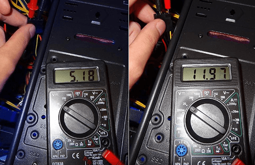
- - 12V (available - 11.7V) - normal
- + 12V2 (12.2V available) - current on a separate 4-pin connector near the processor)
- 5VSB (5.1V) - here V=Volt, SB - "standby" (standby voltage - "standby"), with a nominal value of 5V, which are set at a given level no later than 2 seconds after the unit is connected to the network.
- PG 300ms - "Power Good" signal. Measured in milliseconds (ms). Let's talk about it below :)
- 5V (there is 5.1V) - lines that are used to supply power to hard drives, optical drives, disk drives and other devices.
- + 12V1 (12.2V) - which are fed to the main (20 or 24-pin connector) and disk device connectors.
- + 3.3 V (available - 3.5V) - used to supply power to expansion boards (also present on the SATA connector).
It was we who checked the power supply, which was fully functional (to fill our hand), so to speak :) Now the question is, how to check the power supply of a computer that makes us suspicious? This article began with him, remember? We remove the PSU, "hang" a load (fan) to it and connect it to our tester.

Notice the highlighted areas. We see that the voltage of the computer's power supply along the lines 12V1 and 12V2 is 11.3 V (at a nominal value of 12V).
Is it good or bad? Ask you:) I answer: according to the standard, there are clearly defined boundaries of permissible values that are considered "normal". Everything that does not fit into them - sometimes it also works great, but often it is buggy or does not turn on at all :)
For clarity, here is a table of permissible voltage spread:

The first column shows us all the main lines that are in the BP. Column " Tolerance" this is the maximum allowable deviation from the norm (in percent). According to it, in the field " min" indicates the minimum allowable value for this line. Column " nom" gives the nominal (recommended value, according to the standard). And - " Max" is the maximum allowable.
As you can see (in one of the previous photos), our measurement result for the 12V1 and 12V1 lines is 11.30V and it does not fit into the standard five percent spread (from 11.40 to 12.60V). This malfunction of the power supply, apparently, leads to the fact that in general or it starts from the third time.
So, we found a suspicious malfunction. But how to make an additional check and make sure that the problem is in the low voltage + 12V? With the help of our (most common) multimeter under the brand name " XL830L».
How to check the power supply with a multimeter?
We will start the block as described in, closing two contacts (pins) with a paper clip or a piece of wire of a suitable diameter.

Now - we connect an external fan to the PSU (remember about the "load") and - a 220V cable. If we did everything correctly, then the external fan and the "carlson" on the block itself will begin to rotate. The picture, at this stage, looks like this:

The photo shows the devices with which we will check the power supply. We already considered the work of a tester from China at the beginning of the article, now we will make the same measurements, but with the help of .
Here you need to digress a little and take a closer look at the computer's power supply connector itself. More precisely, the tensions that are present in it. As we can see (in one of the previous photos), it consists of 20 (or 24-four) wires of different colors.
These colors are used for a reason, but they mean very specific things:
- Black the color is "ground" (COM, it is also a common wire or - mass)
- Yellow color + 12V
- Red: +5V
- Orange color: +3.3V
I propose to check and consider each pin separately:

So - much clearer, isn't it? Do you remember colors? (black, yellow, red and orange). This is the main thing that we need to remember and understand before we check the power supply ourselves. But there are a few more pins that we need to pay attention to.
First of all, these are the wires:
- Green PS-ON - when it is shorted to ground, the power supply starts up. This is shown in the diagram as "PSU On". It is these two contacts that we close with a paper clip. The voltage on it should be 5V.
- Further - gray and the signal "Power Good" or "Power OK" transmitted through it. Also 5V (see note)
- Immediately behind it is purple with the marking 5VSB (5V Standby). This is five volts of standby voltage ( duty room). It is supplied to the computer even when it is turned off (the 220V cable must, of course, be connected). This is necessary, for example, in order to be able to send remote computer command over the network to launch "Wake On Lan".
- White (minus five volts) - now practically not used. Previously, it served to provide current for expansion cards installed in the ISA slot.
- Blue (minus twelve volts) - on this moment consume "RS232" interfaces ( COM port), "FireWire" and some PCI expansion cards.
Before checking the power supply with a multimeter, let's consider two more of its connectors: an additional 4-pin for the needs of the processor and a "Molex" connector for connecting optical drives.

Here we see the colors already familiar to us (yellow, red and black) and their corresponding values: + 12 and + 5V.
For greater clarity, download all the PSU voltages in a separate archive.
Now let's make sure that the theoretical knowledge we have received is fully confirmed in practice. In what way? I suggest starting with a careful study of the factory "sticker" (sticker) on one of the real ATX standard power supplies.

Pay attention to what is underlined in red. "DC OUTPUT" (Direct Current Output - DC output value).
- +5V=30A (RED) - plus five IN, provides a current strength of 30 Amperes (red wire) We remember from the text above that it is + 5V that comes in red?
- +12V=10A (YELLOW) - plus twelve IN we have a current of ten amperes (her wire is yellow)
- +3.3V=20A (ORANGE) - line three and three tenths IN can withstand a current of twenty amps (orange)
- -5V (WHITE) - minus five IN- similar to the one described above (white)
- -12V (BLUE) - minus twelve IN(blue)
- +5Vsb (PURPLE) - plus five IN on duty (Standby). We have already talked about him above (he is purple).
- PG (GRAY) - Power Good signal (gray).
On a note: if, for example, the standby voltage, according to measurements, is not equal to five volts, but, say, four, then it is very likely that we are dealing with a problematic voltage stabilizer (zener diode), which should be replaced with a similar one.
And the last entry from the list above tells us that the maximum output power of the product in watts is 400W, and only channels in 3 and 5V can provide a total of 195 watts.
Note: « Power good"- "Food meets the norm." Voltage from 3 to 6 Volts (nominal - 5V) is generated after the necessary internal checks through 100 - 500ms(milliseconds, it turns out - from 0.1 to 0.5 seconds) after switching on. After that, the clock generator chip generates a signal initial installation. If it is absent, then another signal appears on the motherboard - hard reset CPU, preventing the computer from operating on an abnormal or unstable power supply.
If the output voltages do not correspond to the nominal ones (for example, when it decreases in the mains), the Power Good signal disappears and the processor automatically restarts. When all necessary current values are restored "P.G." re-formed and the computer starts working as if it had just been turned on. By quickly turning off the “Power Good” signal, the PC “does not notice” problems in the power system, because it stops work before errors and other problems associated with its instability can appear.
In a properly designed block, the issuance of the “Power Good” command is delayed until power is stabilized on all circuits. In cheap PSUs, this delay is insufficient and the processor starts to work too early, which, in itself, can even lead to distortion of the contents of the CMOS memory.
Now, armed with the necessary theoretical knowledge, we understand how to properly check the power supply of a computer using a multitester. We set the measurement limit on the DC scale to 20 Volts and proceed to check the power supply.

We apply the black "probe" of the tester to the black wire "ground", and we begin to "poke" with red into all the remaining ones :)
Notes e: do not worry, even if you start to "feel" something wrong, you will not burn anything - you will simply get incorrect measurement results.
So, what do we see on the screen of the multimeter in the process of checking the power supply?

On the + 12V line, the voltage is 11.37V. Remember, the Chinese tester showed us 11.3 (in principle, a similar value). But it still does not reach the minimum allowable of 11.40V.
Also pay attention to two useful buttons on the tester: "Hold" - holding the measurement readings on the display and "Back Light" - backlighting the screen (when working in poorly lit rooms).

We see - the same (not inspiring confidence) 11.37V.
Now (for the sake of completeness) we need to check the power supply for compliance with the rating of other values. Let's test, for example, five Volts on the same Molex.

Black "probe" to "ground", and red - to the red five-volt pin. Here is the result on the multimeter:

As you can see - the indicators are normal. Similarly, we measure all other wires and compare each result with the nominal value of.
Thus, checking the power supply showed that the device has a very low (relative to the nominal) voltage of + 12V. Let's, for clarity, once again measure the same line (yellow color on an additional 4-pin connector) for a fully functional device.

We see - 11.92V (remember that the minimum allowable value here is 11.40V). So we are well within the tolerance.
But checking the computer's power supply is still half the battle. It is necessary to repair it after that, and we analyzed this point in one of the previous articles, which was called.
I hope that now you yourself, if necessary, will be able to check the power supply of the computer, you will know exactly what voltages should be present at its terminals and act in accordance with this.
Hello, friends! In this article, we will diagnose components using the most powerful computer stability test - OCCT. The OCCT test stands for OverClock Checking Tool. This special utility able to load the components of your computer to the maximum, subjecting them to all possible tests to detect errors. In other words, OCCT can be used to stress test computer for stability.
OCCT notifies the user of found errors. If there are any, then something is really wrong. In everyday work, perhaps errors will not be noticeable, since you do not subject your computer to such loads. But it is very likely to appear in the future sooner or later. It is possible that it will be in the form of . To avoid such surprises, you can and should test your new or updated computer.
According to the developer of OCCT, a 30-minute test will be enough for most users. But for greater reliability, it is desirable to run tests with a duration of 1 hour.
You can and should download OCCT from the official website http://www.ocbase.com/
Go to the Download tab and at the very bottom there will be download links

I like Zip Version since it does not require installation.
Run OCCT.exe
You can see the appearance of the program in the figure below.

The window on the right monitoring may differ slightly. This window is customizable. To do this, click on the orange button in the left window
In the options that open in the last column, you can configure what will be displayed in the Monitoring window

You can see my settings in the picture above.
After these settings, the Monitoring window will look like this:

At the end of the test, the explorer will open at C:\Users\Anton\Documents\OCCT\
In the folder with the current date there will be graphs of various parameters from the download. Everything is clearly shown there.
If errors are found during the test, you will see a warning. What to do in this case, read the Conclusion.
CPU Test - CPU:LINPACK
This test heavily loads only the processor. It warms it up better than CPU:OCCT
Type of testing choose Auto. The duration and periods of inactivity are left as is.

Memory we also leave as it is.
If you have 64 bit system put the corresponding checkbox.
If your processor supports the AVX command system extension, check the corresponding box.
Here is an excerpt from Wikipedia

I have a processor Sandy Bridge supporting AVX so I check the box.
We also set the checkbox Use all logical cores if it is not checked.
We run the test and do not touch the computer for one hour.
At the end of the test, we look at the graphs with temperatures. If during the test no errors were found and the temperatures are normal, then everything is in order. Otherwise, see Conclusion.
Graphics adapter test - GPU:3D
Then set the checkboxes to enable full screen mode and enable error checking.
Shader complexity. When you hover over this field with the mouse, a tooltip is shown below in the Help section

That is, for AMD graphics cards select 7, for NVIDIA - 3. Since I have integrated graphics from Intel, I leave it by default.
Memory usage. Memory limit for testing. It seems to me that it is desirable not to check the box. Let him use as much as he needs.
Frame Limiter I also leave default.
I run the test and do not touch the computer for an hour. Then I look to see if there were errors and look at the graphs with temperatures. If there were no errors, don't worry. Otherwise, see Conclusion.
Power supply test - POWER SUPPLY
Let's go to last tab POWER SUPPLY. In this test, everything that is possible is loaded, and due to this, diagnostics occur. Whether he holds loads or not.
Set the settings as usual

If you have 64 bit Windows, check the 64 bit Linpack box. The remaining checkboxes, if not installed, are also set.
Run the test

I couldn't stand it for an hour, I stopped the test much earlier, since it's impossible to test a 500 W power supply normally with integrated graphics.
After the test is completed, we look for errors and view the graphs. If everything is fine, then you can continue to work further. Otherwise, see Conclusion.
Conclusion
What to do, if computer stability test ended with errors or was overheating detected? First, the simplest possible. Then, if this did not give the desired result, you can. If the video card is under warranty, it is better to take it to service center. If the warranty has passed, you can replace the thermal paste on the graphics chip.
To exclude the power supply from suspicion, you can put another, more powerful one for the duration of the check. If the test does not pass, it is necessary to remove the overclocking, if any. If the processor or video card has not been overclocked and fails during testing, you must bear the warranty. If the latter is over, then you can try to reduce clock frequencies(this can be done using utilities for the motherboard and using). If it does not help, then you should think about replacing the computer or upgrading it.
My vision about normal temperature accessories can be viewed.